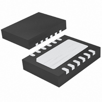
LTC4264IDE#PBF Linear Technology, LTC4264IDE#PBF Datasheet - Page 10

LTC4264IDE#PBF
Manufacturer Part Number
LTC4264IDE#PBF
Description
IC CNTRLR PD INTERFACE 12-DFN
Manufacturer
Linear Technology
Datasheet
1.LTC4264CDEPBF.pdf
(24 pages)
Specifications of LTC4264IDE#PBF
Controller Type
Power over Ethernet Controller (POE)
Interface
IEEE 802.3af
Current - Supply
3mA
Operating Temperature
-40°C ~ 85°C
Mounting Type
Surface Mount
Package / Case
12-DFN
Lead Free Status / RoHS Status
Lead free / RoHS Compliant
Voltage - Supply
-
Available stocks
Company
Part Number
Manufacturer
Quantity
Price
APPLICATIONS INFORMATION
LTC4264
pin high will reduce the signature resistor to 10k which is
an invalid signature per the IEEE 802.3af specifi cations.
This will prevent a PSE from detecting and powering the
PD. This invalid signature is present in the PSE probing
range of –2.8V to –10V. When the input rises above –10V,
the signature resistor reverts to 25k to minimize power
dissipation in the LTC4264. To disable the signature, tie
SHDN to GND. Alternately, the SHDN pin can be driven
high with respect to V
are disabled. For normal operation tie SHDN to V
CLASSIFICATION
Once the PSE has detected a PD, the PSE may option-
ally classify the PD. Classifi cation provides a method for
more effi cient allocation of power by allowing the PSE
10
IN
BY IEEE 802.3af
. When SHDN is high, all functions
DEVICE (PD)
AS DEFINED
INTERFACE
POWERED
Figure 4. PD Front End Using Diode Bridges on Main and Spare Inputs
RJ45
1
2
3
6
4
5
7
8
PSE
TX
TX
RX
RX
TO
+
–
+
–
SPARE
SPARE
Figure 5. 25k Signature Resistor with Disable
+
–
SHDN
V
LTC4264
IN
T1
IN
.
BR2
TO PHY
16k
to identify lower-power PDs and assign the appropriate
power level to these devices. For each class, there is an
associated load current that the PD asserts onto the line
during classifi cation probing. The PSE measures the PD
load current in order to assign the proper PD classifi ca-
tion. Class 0 is included in the IEEE 802.3af specifi cation
to cover PDs that do not support classifi cation. Class 1-3
partition PDs into three distinct power ranges as shown in
Table 2. Class 4 is reserved by the IEEE 802.3af committee
for future use. The new Class 5 defi ned here is available
for system vendors to implement a unique classifi cation
for use in closed systems and is not defi ned or supported
by the IEEE 802.3af. With the extended classifi cation
range available in the LTC4264, it is possible for system
designers to defi ne multiple classes using load currents
between 40mA and 75mA.
SIGNATURE DISABLE
25k SIGNATURE
RESISTOR
0.1µF
100V
BR1
GND
4264 F05
D3
V
IN
LTC4264
GND
4264 F04
4264f


