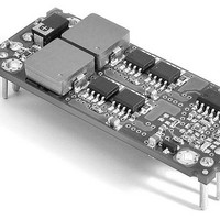
HEN-1.5/25-D12M-C Murata Power Solutions Inc, HEN-1.5/25-D12M-C Datasheet - Page 9

HEN-1.5/25-D12M-C
Manufacturer Part Number
HEN-1.5/25-D12M-C
Description
DC/DC Converters & Regulators 37.5W 12V-1.5V 25A Eighth-Brick
Manufacturer
Murata Power Solutions Inc
Series
HENr
Datasheet
1.HEN-1.525-D12M-C.pdf
(11 pages)
Specifications of HEN-1.5/25-D12M-C
Output Power
38 W
Input Voltage Range
10.2 V to 13.8 V
Number Of Outputs
1
Output Voltage (channel 1)
1.5 V
Output Current (channel 1)
25 A
Package / Case Size
Eighth Brick
Lead Free Status / Rohs Status
Lead free / RoHS Compliant
Other names
HEN-1.5/25-D12M-C
Automated Assembly Production Notes
DATEL’s new high-efficiency DC/DC converters are designed for modern
surface-mount technology (SMT) automated assembly using screened
solder paste, "pick and place" component positioning and forced hot air
reflow oven soldering. If you are new to SMT techniques and have a volume
application, these features save time, cost and improve manufacturing
efficiency. DATEL’s DC/DC assembly operations themselves make extensive
use of such techniques.
Even if you have previous SMT experience, you should read the sections
below on solder reflow profiles and heat shields. This information is not
intended to replace the documentation for your SMT system. We assume
that you are already experienced with all the components of your SMT
system.
This section will discuss several SMT issues, including:
Mechanical Configuration of Input/Output Connections
These new converters are supplied either using traditional through-hole
pins or SMT leads. (Note that some models are offered only with lead
mounting). The pin options insert into plated-through holes in the host pcb.
Be aware that some heat dissipation is carried off by either the pins or
leads. The Derating Curves assume that some additional pad area is avail-
able on your host pcb to absorb the heat.
The lead option uses either short tabs in "gullwing" style or standoff leads
under the converter. The gullwing leads typically are copper alloy with 150
microinches of tin plating. Solder paste (typically 0.008" to 0.009" thick) is
applied to the host pcb using a solder mask pressure screening technique
and the board is heated and cooled long enough for the solder to reflow
and adhere to both the host pads and the converter’s mounting leads.
After such mounting, the entire mechanical mounting load is carried by the
solder. Obviously the converters must be accurately positioned all during
the solder reflow period. Where solder surface tension is sufficient to force
tiny components into position, these larger converters may not move and
must be accurately positioned by your SMT system.
Part Handling and Supply
SMT eighth- and quarter-brick DC/DC converters (plus installed heat
shields if used) are supplied in JEDEC-standard 5.35" by 12.4" waffle trays
which are compatible with the feeders on industry-standard pick-and-place
machines.
Since the converters are larger and heavier than many other components,
make sure your system can reliably remove the units from their trays, move
I/O Mechanical Configuration
Part Handling and Supply
Printed Circuit Board (pcb) Mounting
Soldering using Reflow Technology
Temperature Profiling
Heat Shields and Removal
www.murata-ps.com
them to the host pcb and accurately position them. The plastic heat shield
(see below) doubles as a vacuum pickup area.
Heatsinks
If you are using the preinstalled heatsink from DATEL, proceed normally
with surface mounting per the information in this section (the heat shield
fits completely over the heatsink). However, if you wish to add the heatsink
after receiving the converters and heatsink separately, you must install the
heatsink before solder reflow. Essentially, install the heatsink then place
the assembled converters back in the tray for surface mount positioning.
Please observe the torquing and assembly procedure discussed earlier for
the heatsink.
Pick and Place pcb Mounting
The main issues here are pad area, orientation, positioning accuracy,
vacuum pickup and coplanarity. DATEL recommends that pcb pads to
interface with the DC/DC converter should be sized as shown in the dia-
gram below. The pads footprint accommodates the positioning accuracy of
your SMT equipment and manufactured tolerances of the DC/DC mounting
leads.
Orientation: When loaded into JEDEC trays, these converters are all
oriented in the same direction. See the diagram below. For the LEN and
HEN series, a notch is placed on the top of the case (on the removal tabs) to
indicate the pin 1 position. You should visually inspect the tray to be sure of
this orientation.
On the bottom of the converter, the LEN and HEN series include optical
fiducial marks viewable by your SMT imaging system. See the attached
diagram. Observing from the bottom, your SMT imaging camera should find
these marks to identify the converter and verify pin 1. On most pick-and-
place systems, during head transit, the imaging system will automatically
fine tune the end mounting position of the converter using image compari-
sons from these fiducials or other reference marks you have chosen.
The fiducial marks are placed fairly close together because most imaging
systems have a one inch or less observing area since most SMT parts are
considerably smaller than these converters. You may prefer to train your
imaging system to use a corner of the converter or an I/O lead.
Single Output, Non Isolated, 12VIN, 0.8-5VOUT
Figure 6. Recommended SMT Mounting Pad Dimensions
Technical enquiries email: sales@murata-ps.com, tel:
25 Amp, High di/dt DC/DC Converters
HEN D12 Models
MDC_HEN-D12.B01 Page 9 of 11
+1 508 339 3000


