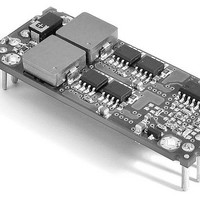
HEN-1.5/25-D12M-C Murata Power Solutions Inc, HEN-1.5/25-D12M-C Datasheet - Page 5

HEN-1.5/25-D12M-C
Manufacturer Part Number
HEN-1.5/25-D12M-C
Description
DC/DC Converters & Regulators 37.5W 12V-1.5V 25A Eighth-Brick
Manufacturer
Murata Power Solutions Inc
Series
HENr
Datasheet
1.HEN-1.525-D12M-C.pdf
(11 pages)
Specifications of HEN-1.5/25-D12M-C
Output Power
38 W
Input Voltage Range
10.2 V to 13.8 V
Number Of Outputs
1
Output Voltage (channel 1)
1.5 V
Output Current (channel 1)
25 A
Package / Case Size
Eighth Brick
Lead Free Status / Rohs Status
Lead free / RoHS Compliant
Other names
HEN-1.5/25-D12M-C
Series DC/DC converters are designed so that they are enabled when the
control pin is left open (or pulled low to 0 to +0.4V) and disabled when the
control pin is pulled high (+2.8V to +V
have an internal 20kΩ pull-down resistor to Common (ground).
Dynamic control of the on/off function is best accomplished with a mechan-
ical relay or open-collector/open-drain drive circuit (optically isolated if
appropriate). The drive circuit should be able to sink appropriate current
when activated and withstand appropriate voltage when deactivated.
The on/off control can be driven using a circuit comparable to that shown in
Figure 2. Leaving the On/Off control pin open or applying a voltage between
0V and +0.4V will turn on the converter. Applied voltages between +2.8V
and +V
Power-up sequencing
If a controlled start-up of one or more HEN D12 Series DC/DC converters
is required, or if several output voltages need to be powered-up in a given
sequence, the On/Off control pin can be pulled high to +V
5.6kΩ resistor. While input voltage and/or other converters are ramping up,
the control pin is pulled high and the converter remains disabled. To enable
the output voltage, the control pin needs to be pulled low in the configura-
tion shown in Figure 3.
Output Overvoltage Protection
The HEN D12 Series output voltage is monitored. If the output voltage
rises to a level, which could be damaging to the load, the internal sensing
circuitry will power down the PWM controller causing the output voltage
to decrease. Following a time-out period the PWM will restart, causing
the output voltage to ramp to its appropriate value. If the fault condition
persists, and the output voltage again climbs to excessive levels, the over-
voltage circuitry will initiate another shutdown cycle. This on/off cycling is
referred to as "hiccup" mode.
Output Overcurrent Detection
Overloading the power converter's output for an extended time will invari-
ably cause internal component temperatures to exceed their maximum
ratings and eventually lead to component failure. High-current-carrying
components such as inductors, FET's and diodes are at the highest risk.
HEN D12 Series DC/DC converters incorporate an output overcurrent detec-
tion and shutdown function that serves to protect both the power converter
and its load.
If the output current exceeds it maximum rating by typically 40% (35 Amps)
or if the output voltage drops to less than 98% of it original value, the HEN
Figure 3. Driving The Power-Up With An External Pull-up Resistor
IN
will disable the converter.
External Input Open:
External Input Low:
On/Off pin High = DC/DC converter Off
On/Off pin Low = DC/DC converter On
IN
). As shown in Figure 2, all models
www.murata-ps.com
IN
with an external
D12's internal overcurrent-detection circuitry immediately turns off the
converter, which then goes into a "hiccup" mode. While hiccupping, the
converter will continuously attempt to restart itself, go into overcurrent, and
then shut down. Under these conditions, both the average output current
and the average input current will be kept extremely low. Once the output
short is removed, the converter will automatically restart itself.
Output Voltage Trimming
Allowable trim ranges are ±10%. Trimming is accomplished with either a
trimpot or a single fixed resistor. The trimpot should be connected between
+Output and Common with its wiper connected to the Trim pin as shown in
Figure 4 below.
A trimpot can be used to determine the value of a single fixed resistor
which can then be connected, as shown in Figure 5, between the Trim pin
and +Output to trim down the output voltage, or between the Trim pin and
Common to trim up the output voltage. Fixed resistors should have absolute
TCR’s less than 100ppm/°C to ensure stability.
The equations below can be starting points for selecting specific trim-resistor
values. Recall, untrimmed devices are guaranteed to be ±1.5% accurate.
Adjustment beyond the specified ±10% adjustment range is not recommended.
Note: Resistor values are in kΩ. Accuracy of adjustment is subject to
tolerances of resistors and factory-adjusted, initial output accuracy.
V
O
Single Output, Non Isolated, 12VIN, 0.8-5VOUT
= desired output voltage. V
Figure 5. Trim Connections Using Fixed Resistors
Figure 4. Trim Connections Using a Trimpot
Technical enquiries email: sales@murata-ps.com, tel:
25 Amp, High di/dt DC/DC Converters
Trim Equations
HEN D12 Models
O
NOM
= nominal output voltage.
MDC_HEN-D12.B01 Page 5 of 11
Note:
Install either a fixed
trim-up resistor
or a fixed trim-down
resistor depending upon
desired output voltage.
+1 508 339 3000


