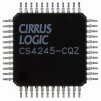
CS4245-CQZ Cirrus Logic Inc, CS4245-CQZ Datasheet - Page 4

CS4245-CQZ
Manufacturer Part Number
CS4245-CQZ
Description
IC CODEC AUD STER 104DB 48LQFP
Manufacturer
Cirrus Logic Inc
Type
Stereo Audior
Datasheet
1.CS4245-CQZ.pdf
(57 pages)
Specifications of CS4245-CQZ
Package / Case
48-LQFP
Data Interface
Serial
Resolution (bits)
24 b
Number Of Adcs / Dacs
2 / 2
Sigma Delta
Yes
Dynamic Range, Adcs / Dacs (db) Typ
104 / 104
Voltage - Supply, Analog
3.13 V ~ 5.25 V
Voltage - Supply, Digital
3.13 V ~ 5.25 V
Operating Temperature
-10°C ~ 70°C
Mounting Type
Surface Mount
Number Of Adc Inputs
12
Number Of Dac Outputs
4
Conversion Rate
192 KSPS
Interface Type
Serial (I2C, SPI)
Resolution
24 bit
Operating Supply Voltage
3.3 V, 5 V
Maximum Operating Temperature
+ 70 C
Mounting Style
SMD/SMT
Minimum Operating Temperature
- 10 C
Number Of Channels
2 ADC/2 DAC
Thd Plus Noise
- 95 dB ADC / - 90 dB DAC
Lead Free Status / RoHS Status
Lead free / RoHS Compliant
For Use With
598-1501 - BOARD EVAL FOR CS4245 CODEC
Lead Free Status / Rohs Status
Lead free / RoHS Compliant
Other names
598-1034
Available stocks
Company
Part Number
Manufacturer
Quantity
Price
Company:
Part Number:
CS4245-CQZ
Manufacturer:
CIRRUS
Quantity:
455
Part Number:
CS4245-CQZ
Manufacturer:
CIRRUS
Quantity:
20 000
Company:
Part Number:
CS4245-CQZR
Manufacturer:
Schneider
Quantity:
1 000
Company:
Part Number:
CS4245-CQZR
Manufacturer:
Cirrus Logic Inc
Quantity:
10 000
4
LIST OF FIGURES
7. PARAMETER DEFINITIONS ................................................................................................................ 50
8. DAC FILTER PLOTS
9. ADC FILTER PLOTS
10. PACKAGE DIMENSIONS .................................................................................................................. 55
11. THERMAL CHARACTERISTICS AND SPECIFICATIONS ............................................................. 55
12. ORDERING INFORMATION
13. REVISION HISTORY .......................................................................................................................... 56
Figure 1.DAC Output Test Load ................................................................................................................ 11
6.3 DAC Control - Address 03h ............................................................................................................ 41
6.4 ADC Control - Address 04h ............................................................................................................ 42
6.5 MCLK Frequency - Address 05h .................................................................................................... 43
6.6 Signal Selection - Address 06h ...................................................................................................... 44
6.7 Channel B PGA Control - Address 07h .......................................................................................... 45
6.8 Channel A PGA Control - Address 08h .......................................................................................... 45
6.9 ADC Input Control - Address 09h ................................................................................................... 45
6.10 DAC Channel A Volume Control - Address 0Ah ........................................................................... 46
6.11 DAC Channel B Volume Control - Address 0Bh ........................................................................... 46
6.12 DAC Control 2 - Address 0Ch ...................................................................................................... 47
6.13 Interrupt Status - Address 0Dh ..................................................................................................... 48
6.14 Interrupt Mask - Address 0Eh ....................................................................................................... 48
6.15 Interrupt Mode MSB - Address 0Fh .............................................................................................. 49
6.16 Interrupt Mode LSB - Address 10h ............................................................................................... 49
6.2.4 Power-Down DAC (Bit 1) ....................................................................................................... 41
6.2.5 Power-Down Device (Bit 0) ................................................................................................... 41
6.3.1 DAC Functional Mode (Bits 7:6) ............................................................................................ 41
6.3.2 DAC Digital Interface Format (Bits 5:4) ................................................................................. 41
6.3.3 Mute DAC (Bit 2) ................................................................................................................... 41
6.3.4 De-Emphasis Control (Bit 1) .................................................................................................. 42
6.3.5 DAC Master / Slave Mode (Bit 0) .......................................................................................... 42
6.4.1 ADC Functional Mode (Bits 7:6) ............................................................................................ 42
6.4.2 ADC Digital Interface Format (Bit 4) ...................................................................................... 43
6.4.3 Mute ADC (Bit 2) ................................................................................................................... 43
6.4.4 ADC High-Pass Filter Freeze (Bit 1) ..................................................................................... 43
6.4.5 ADC Master / Slave Mode (Bit 0) .......................................................................................... 43
6.5.1 Master Clock 1 Frequency (Bits 6:4) ..................................................................................... 43
6.5.2 Master Clock 2 Frequency (Bits 2:0) ..................................................................................... 44
6.6.1 Auxiliary Output Source Select (Bits 6:5) .............................................................................. 44
6.6.2 Digital Loopback (Bit 1) ......................................................................................................... 44
6.6.3 Asynchronous Mode (Bit 0) ................................................................................................... 44
6.7.1 Channel B PGA Gain (Bits 5:0) ............................................................................................. 45
6.8.1 Channel A PGA Gain (Bits 5:0) ............................................................................................. 45
6.9.1 PGA Soft Ramp or Zero Cross Enable (Bits 4:3) .................................................................. 45
6.9.2 Analog Input Selection (Bits 2:0) ........................................................................................... 46
6.11.1 Volume Control (Bits 7:0) .................................................................................................... 46
6.12.1 DAC Soft Ramp or Zero Cross Enable (Bits 7:6) ................................................................ 47
6.12.2 Invert DAC Output (Bit 5) .................................................................................................... 47
6.12.3 Active High/Low (Bit 0) ........................................................................................................ 48
6.13.1 ADC Clock Error (Bit 3) ....................................................................................................... 48
6.13.2 DAC Clock Error (Bit 2) ....................................................................................................... 48
6.13.3 ADC Overflow (Bit 1) ........................................................................................................... 48
6.13.4 ADC Underflow (Bit 0) ......................................................................................................... 48
......................................................................................................................... 53
.................................................................................................................... 51
..................................................................................................... 56
CS4245
DS656F2


