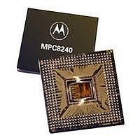
XPC8240RZU250E Freescale Semiconductor, XPC8240RZU250E Datasheet - Page 38

XPC8240RZU250E
Manufacturer Part Number
XPC8240RZU250E
Description
MCU HOST PROCESSOR 352-TBGA
Manufacturer
Freescale Semiconductor
Series
PowerQUICC IIr
Specifications of XPC8240RZU250E
Processor Type
MPC82xx PowerQUICC II 32-bit
Speed
200MHz
Voltage
2.5V
Mounting Type
Surface Mount
Package / Case
352-TBGA
Core Size
32 Bit
Program Memory Size
32KB
Cpu Speed
250MHz
Embedded Interface Type
I2C
Digital Ic Case Style
TBGA
No. Of Pins
352
Supply Voltage Range
2.5V To 2.75V
Rohs Compliant
No
Family Name
MPC82XX
Device Core Size
32b
Frequency (max)
250MHz
Instruction Set Architecture
RISC
Supply Voltage 1 (typ)
2.625/2.6255V
Operating Supply Voltage (max)
2.75625/2.756775V
Operating Supply Voltage (min)
2.49375/2.494225V
Operating Temp Range
0C to 105C
Operating Temperature Classification
Commercial
Mounting
Surface Mount
Pin Count
352
Package Type
TBGA
Lead Free Status / RoHS Status
Contains lead / RoHS non-compliant
Features
-
Lead Free Status / Rohs Status
Not Compliant
Available stocks
Company
Part Number
Manufacturer
Quantity
Price
Company:
Part Number:
XPC8240RZU250E
Manufacturer:
MOT
Quantity:
12 388
Company:
Part Number:
XPC8240RZU250E
Manufacturer:
MOTOLOLA
Quantity:
513
Company:
Part Number:
XPC8240RZU250E
Manufacturer:
Freescale Semiconductor
Quantity:
10 000
Part Number:
XPC8240RZU250E
Manufacturer:
FREESCALE
Quantity:
20 000
Freescale Semiconductor, Inc.
System Design Information
System Design Information
interface connects primarily through the JTAG port of the processor, with some additional status monitoring
signals. The COP port requires the ability to independently assert HRESET or TRST in order to fully control
the processor. If the target system has independent reset sources, such as voltage monitors, watchdog timers,
power supply failures, or push-button switches, the COP reset signals must be merged into these signals with
logic.
The arrangement shown in Figure 25 allows the COP to independently assert HRESET or TRST, while
ensuring that the target can drive HRESET as well. If the JTAG interface and COP header will not be used,
TRST should be tied to HRESET so that it is asserted when the system reset signal (HRESET) is asserted
ensuring that the JTAG scan chain is initialized during power-on.
The COP header shown in Figure 25 adds many benefits—breakpoints, watchpoints, register and memory
examination/modification, and other standard debugger features are possible through this interface—and
can be as inexpensive as an unpopulated footprint for a header to be added when needed.
The COP interface has a standard header for connection to the target system, based on the 0.025"
square-post, 0.100" centered header assembly (often called a Berg header).
There is no standardized way to number the COP header shown in Figure 25; consequently, many different
pin numbers have been observed from emulator vendors. Some are numbered top-to-bottom then
left-to-right, while others use left-to-right then top-to-bottom, while still others number the pins counter
clockwise from pin 1 (as with an IC). Regardless of the numbering, the signal placement recommended in
Figure 25 is common to all known emulators.
38
MPC8240 Integrated Processor Hardware Specifications
For More Information On This Product,
Go to: www.freescale.com


