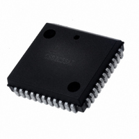
CS80C286-16 Intersil, CS80C286-16 Datasheet - Page 14

CS80C286-16
Manufacturer Part Number
CS80C286-16
Description
IC CPU 16BIT 5V 16MHZ 68-PLCC
Manufacturer
Intersil
Datasheet
1.CS80C286-12.pdf
(60 pages)
Specifications of CS80C286-16
Processor Type
80C286 16-Bit
Speed
16MHz
Voltage
5V
Mounting Type
Surface Mount
Package / Case
68-PLCC
Lead Free Status / RoHS Status
Contains lead / RoHS non-compliant
Features
-
Available stocks
Company
Part Number
Manufacturer
Quantity
Price
Company:
Part Number:
CS80C286-16
Manufacturer:
INTERSIL
Quantity:
15
Company:
Part Number:
CS80C286-16
Manufacturer:
HARRIS
Quantity:
5
Company:
Part Number:
CS80C286-16
Manufacturer:
INTERSIL
Quantity:
5 510
Part Number:
CS80C286-16
Manufacturer:
HARRIS
Quantity:
20 000
Single Step Interrupt
The 80C286 has an internal interrupt that allows programs to
execute one instruction at a time. It is called the single step
interrupt and is controlled by the single step flag bit (TF) in the
flag word. Once this bit is set, an internal single step interrupt
will occur after the next instruction has been executed. The
interrupt clears the TF bit and uses an internally supplied vec-
tor of 1. The lRET instruction is used to set the TF bit and
transfer control to the next instruction to be single stepped.
Interrupt Priorities
When simultaneous interrupt requests occur, they are pro-
cessed in a fixed order as shown in Table 5. Interrupt pro-
cessing involves saving the flags, return address, and
setting CS:lP to point at the first instruction of the interrupt
handler. If another enabled interrupt should occur, it is pro-
cessed before the next instruction of the current interrupt
handler is executed. The last interrupt processed is therefore
the first one serviced.
Initialization and Processor Reset
Processor initialization or start up is accomplished by driving
the RESET input pin HIGH. RESET forces the 80C286 to
terminate all execution and local bus activity. No instruction
or bus activity will occur as long as RESET is active. After
RESET becomes inactive, and an internal processing inter-
val elapses, the 80C286 begins execution in real address
mode with the instruction at physical location FFFFF0(H).
RESET also sets some registers to predefined values as
shown in Table 6.
HOLD must not be active during the time from the leading
edge of the initial RESET to 34 CLKs after the trailing edge
of the initial RESET of an 80C286 system.
Flag Word
Machine Status Word
Instruction Pointer
Code Segment
Data Segment
Extra Segment
Stack Segment
TABLE 6. 80C286 INITIAL REGISTER STATE AFTER RESET
ORDER
1
2
3
4
5
6
TABLE 5. INTERRUPT PROCESSING ORDER
Instruction Exception
Single Step
NMI
Processor Extension Segment Overrun
INTR
INT Instruction
INTERRUPT
FFF0(H)
FFF0(H)
0002(H)
F000(H)
0000(H)
0000(H)
0000(H)
80C286
14
Machine Status Word Description
The machine status word (MSW) records when a task switch
takes place and controls the operating mode of the 80C286.
It is a 16-bit register of which the lower four bits are used.
One bit places the CPU into protected mode, while the other
three bits, as shown in Table 7, control the processor exten-
sion interface. After RESET, this register contains FFF0(H)
which places the 80C286 in 80C286 real address mode.
The LMSW and SMSW instructions can load and store the
MSW in real address mode. The recommended use of TS,
EM, and MP is shown in Table 8.
Halt
The HLT instruction stops program execution and prevents
the CPU from using the local bus until restarted. Either NMI,
INTR with IF = 1, or RESET will force the 80C286 out of halt.
If interrupted, the saved CS:IP will point to the next instruc-
tion after the HLT.
POSITION
BIT
0
1
2
3
NAME
TABLE 7. MSW BIT FUNCTIONS
MP
EM
PE
TS
Protected mode enable places the
80C286 into protected mode and cannot
be cleared except by RESET.
Monitor processor extension allows WAIT
instructions to cause a processor exten-
sion not present exception (number 7).
Emulate processor extension causes a
processor extension not present excep-
tion (number 7) on ESC instructions to al-
low emulating a processor extension.
Task switched indicates the next instruc-
tion using a processor extension will
cause exception 7, allowing software to
test whether the current processor exten-
sion context belongs to the current task.
FUNCTION


