N80960SA10 Intel, N80960SA10 Datasheet - Page 25
N80960SA10
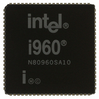
Manufacturer Part Number
N80960SA10
Description
IC MPU I960SA 10MHZ 84-PLCC
Manufacturer
Intel
Datasheet
1.N80960SA10.pdf
(39 pages)
Specifications of N80960SA10
Rohs Status
RoHS non-compliant
Processor Type
i960
Features
SA suffix, 32-Bit, 512 Byte Cache
Speed
10MHz
Voltage
5V
Mounting Type
Surface Mount
Package / Case
84-PLCC
Other names
803819
Available stocks
Company
Part Number
Manufacturer
Quantity
Price


3.0
3.1
The 80960SA is available in two package types:
•
•
Dimensions for both package types are given in the
Intel Packaging handbook (Order #240800).
READY
80-lead quad flat pack (EIAJ QFP). Shown in
Figure 15.
84-lead plastic leaded chip carrier (PLCC).
Shown in Figure 16.
ALE
V
V
V
A31
A30
A29
A28
V
A27
A26
A25
V
A24
A23
CC
CC
SS
SS
SS
MECHANICAL DATA
Packaging
65
66
67
68
69
70
71
72
73
74
75
76
77
78
79
80
64 63 62 61 60 59 58 57 56 55 54 53 52 51 50 49 48 47 46 45 44 43 42 41
1
2 3 4
Figure 15. 80-Lead EIAJ Quad Flat Pack (QFP) Package
5
6
7 8
9 10 11 12 13 14 15 16 17 18 19 20 21
S80960SA-20
XXXXXXXX
XXXXXX
XXXXXX
3.2
The QFP and PLCC have different pin assignments.
The QFP pins are numbered in order from 1 to 80
around the package perimeter. The PLCC pins are
numbered in order from 1 to 84 around the package
perimeter. Tables 9 and 10 list the function of each
QFP pin; Tables 11 and 12 list the function of each
PLCC pin.
V
V
connected to the appropriate voltage or ground and
externally strapped close to the package. It is recom-
mended that you include separate power and ground
planes in your circuit board for power distribution.
Pins identified as NC (No Connect) should never be
connected
CC
CC
and GND connections must be made to multiple
and GND pins. Each V
Pin Assignment
.
22 23 24
CC
and GND pin must be
40
39
38
37
36
35
34
33
32
31
30
29
28
27
26
25
80960SA
BE1
NC
A1
V
V
A2
A3
V
V
D0
AD1
AD2
AD3
AD4
AD5
AD6
SS
CC
CC
SS
21
Related parts for N80960SA10
Image
Part Number
Description
Manufacturer
Datasheet
Request
R

Part Number:
Description:
Microprocessor: Intel Celeron M Processor 320 and Ultra Low Voltage Intel Celeron M Processor at 600MHz
Manufacturer:
Intel Corporation
Part Number:
Description:
Intel 82550 Fast Ethernet Multifunction PCI/CardBus Controller
Manufacturer:
Intel Corporation
Datasheet:
Part Number:
Description:
Intel StrataFlash memory 32 Mbit. Access speed 120 ns
Manufacturer:
Intel Corporation
Datasheet:
Part Number:
Description:
Intel StrataFlash memory 32 Mbit. Access speed 120 ns
Manufacturer:
Intel Corporation
Datasheet:
Part Number:
Description:
Intel StrataFlash memory 64 Mbit. Access speed 150 ns
Manufacturer:
Intel Corporation
Datasheet:
Part Number:
Description:
Intel StrataFlash memory 32 Mbit. Access speed 100 ns
Manufacturer:
Intel Corporation
Datasheet:
Part Number:
Description:
DA28F640J5A-1505 Volt Intel StrataFlash Memory
Manufacturer:
Intel Corporation
Datasheet:
Part Number:
Description:
5 Volt Intel StrataFlash?? Memory
Manufacturer:
Intel Corporation
Datasheet:
Part Number:
Description:
5 Volt Intel StrataFlash?? Memory
Manufacturer:
Intel Corporation
Part Number:
Description:
Intel 6300ESB I/O Controller Hub
Manufacturer:
Intel Corporation
Datasheet:
Part Number:
Description:
Intel 82801DB I/O Controller Hub (ICH4), Pb-Free SLI
Manufacturer:
Intel Corporation
Datasheet:
Part Number:
Description:
Intel 82801FB I/O Controller Hub (ICH6)
Manufacturer:
Intel Corporation
Datasheet:
Part Number:
Description:
Intel Strataflash Memory28F128J3 28F640J3 28F320J3
Manufacturer:
Intel Corporation
Datasheet:
Part Number:
Description:
Controllers, Intel 430TX PCIset: 82439TX System Controller (MTXC)
Manufacturer:
Intel Corporation