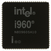
N80960SA10 Intel, N80960SA10 Datasheet - Page 12

N80960SA10
Manufacturer Part Number
N80960SA10
Description
IC MPU I960SA 10MHZ 84-PLCC
Manufacturer
Intel
Datasheet
1.N80960SA10.pdf
(39 pages)
Specifications of N80960SA10
Rohs Status
RoHS non-compliant
Processor Type
i960
Features
SA suffix, 32-Bit, 512 Byte Cache
Speed
10MHz
Voltage
5V
Mounting Type
Surface Mount
Package / Case
84-PLCC
Other names
803819
Available stocks
Company
Part Number
Manufacturer
Quantity
Price
80960SA
8
CLK2
A31:16
AD15:1, D0
A3:1
ALE
AS
W/R
DEN
DT/R
READY
I/O = Input/Output, O = Output, I = Input, O.D. = Open Drain, T.S. = Three-state
NAME
TYPE
T.S.
T.S.
T.S.
T.S.
T.S.
T.S.
T.S.
T.S.
I/O
O
O
O
O
O
O
O
I
I
Table 3. 80960SA Pin Description: Bus Signals (Sheet 1 of 2)
SYSTEM CLOCK provides the fundamental timing for 80960SA systems. It is
divided by two inside the 80960SA to generate the internal processor clock.
ADDRESS BUS carries the upper 16 bits of the 32-bit physical address to memory.
It is valid throughout the burst cycle; no latch is required.
ADDRESS/DATA BUS carries the low order 32-bit addresses and 16-bit data to
and from memory. AD15:4 must be latched since the cycle following the address
cycle carries data on the bus.
ADDRESS BUS carries the word addresses of the 32-bit address to memory.
These three bits are incremented during a burst access indicating the next word
address of the burst access. Note that A3:1 are duplicated with AD3:1 during the
address cycle.
ADDRESS LATCH ENABLE indicates the transfer of a physical address. ALE is
asserted during a T
active HIGH and floats to a high impedance state during a hold cycle (T
ADDRESS STATUS indicates an address state. AS is asserted every T
deasserted during the following T
WRITE/READ specifies, during a T
It is latched on-chip and remains valid during T
DATA ENABLE is asserted during T
AD lines. The AD lines should not be driven by an external source unless DEN is
asserted. When DEN is asserted, outputs from the previous cycle are guaranteed
to be three-stated. In addition, DEN deasserted indicates inputs have been
captured; therefore input hold times can be disregarded. DEN is driven HIGH
during reset.
DATA TRANSMIT / RECEIVE indicates the direction of data transfer to and from
the bus. It is low during T
is high during T
asserted. DT/R is driven HIGH during reset.
READY indicates that data on AD lines can be sampled or removed. If READY is
not asserted during a T
inserting a wait state (T
a
and T
a
cycle and deasserted before the beginning of the T
d
w
d
cycles for a write. DT/R never changes state when DEN is
).
a
cycle, the T
and T
d
d
DESCRIPTION
cycles for a read or interrupt acknowledgment; it
a
state. AS is driven HIGH during reset.
cycle, whether the operation is a write or read.
d
d
cycles and indicates transfer of data on the
cycle is extended to the next cycle by
d
cycles.
a
d
h
).
state and
state. It is


