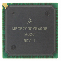
MPC5200CVR400B Freescale Semiconductor, MPC5200CVR400B Datasheet - Page 40

MPC5200CVR400B
Manufacturer Part Number
MPC5200CVR400B
Description
IC MPU 32BIT 400MHZ 272-PBGA
Manufacturer
Freescale Semiconductor
Specifications of MPC5200CVR400B
Processor Type
MPC52xx PowerPC 32-Bit
Speed
400MHz
Voltage
1.5V
Mounting Type
Surface Mount
Package / Case
272-PBGA
Processor Series
MPC52xx
Core
e300
Development Tools By Supplier
MEDIA5200KIT1E
Maximum Clock Frequency
400 MHz
Maximum Operating Temperature
+ 105 C
Mounting Style
SMD/SMT
I/o Voltage
2.5 V, 3.3 V
Minimum Operating Temperature
- 40 C
Core Size
32 Bit
No. Of I/o's
56
Ram Memory Size
16KB
Cpu Speed
400MHz
No. Of Timers
8
Embedded Interface Type
CAN, I2C, SCI, SPI
No. Of Pwm Channels
8
Digital Ic Case Style
TEPBGA
Rohs Compliant
Yes
Lead Free Status / RoHS Status
Lead free / RoHS Compliant
Features
-
Lead Free Status / Rohs Status
Lead free / RoHS Compliant
Available stocks
Company
Part Number
Manufacturer
Quantity
Price
Company:
Part Number:
MPC5200CVR400B
Manufacturer:
Marvell
Quantity:
1 001
Company:
Part Number:
MPC5200CVR400B
Manufacturer:
FREESCAL
Quantity:
200
Company:
Part Number:
MPC5200CVR400B
Manufacturer:
Freescale Semiconductor
Quantity:
10 000
Part Number:
MPC5200CVR400B
Manufacturer:
FREESCALE
Quantity:
20 000
Company:
Part Number:
MPC5200CVR400BM62C
Manufacturer:
FRRESCAL..
Quantity:
2 831
1.3.11
40
1
2
1
Sym
MDC is generated by MPC5200B with a duty cycle of 50% except when MII_SPEED in the FEC MII_SPEED control
register is changed during operation. See the MPC5200B User’s Manual (MPC5200BUM).
The MDC period must be set to a value of less than or equal to 2.5 MHz (to be compliant with the IEEE MII
characteristic) by programming the FEC MII_SPEED control register. See the MPC5200B User’s Manual
(MPC5200BUM).
Defined in the USB config register, (12 Mbit/s or 1.5 Mbit/s mode).
Sym
t
t
t
t
t
t
10
11
12
13
14
15
1
2
3
4
USB
MDIO (Output)
MDC (Output)
MDIO (Input)
MDIO (input) to MDC rising edge setup
MDC falling edge to MDIO output delay
MDIO (input) to MDC rising edge hold
Figure 30. Ethernet Timing Diagram—MII Serial Management
MDC pulse width high
MDC pulse width low
Table 34. MII Serial Management Channel Signal Timing
Transceiver enable time
Table 35. Timing Specifications—USB Output Line
MDC period
Description
Signal falling time
Signal rising time
USB Bit width
Output timing is specified at a nominal 50 pF load.
Description
(2)
t
MPC5200B Data Sheet, Rev. 4
11
(1)
(1)
(1)
t
12
t
13
NOTE
t
15
t
10
Min
160
160
400
10
10
t
0
14
83.3
83.3
Min
—
—
Max
25
—
—
—
—
—
Max
667
667
7.9
7.9
Unit
ns
ns
ns
ns
ns
ns
Units
Freescale Semiconductor
ns
ns
ns
ns
SpecID
SpecID
A9.10
A9.11
A9.12
A9.13
A9.14
A9.15
A10.1
A10.2
A10.3
A10.4


