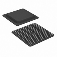
XC3S1200E-4FGG320I Xilinx Inc, XC3S1200E-4FGG320I Datasheet - Page 94

XC3S1200E-4FGG320I
Manufacturer Part Number
XC3S1200E-4FGG320I
Description
IC FPGA SPARTAN-3E 1200K 320FBGA
Manufacturer
Xilinx Inc
Series
Spartan™-3Er
Datasheet
1.XC3S100E-4VQG100C.pdf
(233 pages)
Specifications of XC3S1200E-4FGG320I
Number Of Logic Elements/cells
19512
Number Of Labs/clbs
2168
Total Ram Bits
516096
Number Of I /o
250
Number Of Gates
1200000
Voltage - Supply
1.14 V ~ 1.26 V
Mounting Type
Surface Mount
Operating Temperature
-40°C ~ 100°C
Package / Case
320-BGA
Lead Free Status / RoHS Status
Lead free / RoHS Compliant
Available stocks
Company
Part Number
Manufacturer
Quantity
Price
Company:
Part Number:
XC3S1200E-4FGG320I
Manufacturer:
Xilinx Inc
Quantity:
10 000
Part Number:
XC3S1200E-4FGG320I
Manufacturer:
XILINX/赛灵思
Quantity:
20 000
- Current page: 94 of 233
- Download datasheet (6Mb)
Functional Description
After the FPGA configures itself using BPI mode from one
end of the parallel Flash PROM, then the FPGA can trigger
a MultiBoot event and reconfigure itself from the opposite
end of the parallel Flash PROM. MultiBoot is only available
when using BPI mode and only for applications with a single
Spartan-3E FPGA.
By default, MultiBoot mode is disabled. To trigger a Multi-
Boot event, assert a Low pulse lasting at least 300 ns on the
MultiBoot Trigger (MBT) input to the STARTUP_SPARTAN3E
library primitive. When the MBT signal returns High after the
300 ns or longer pulse, the FPGA automatically reconfig-
ures from the opposite end of the parallel Flash memory.
Figure 60
loads itself from the attached parallel Flash PROM. In this
In another potential application, the initial design loaded into
the FPGA image contains a “golden” or “fail-safe” configura-
tion image, which then communicates with the outside world
and checks for a newer image. If there is a new configura-
tion revision and the new image verifies as good, the
“golden” configuration triggers a MultiBoot event to load the
new image.
When a MultiBoot event is triggered, the FPGA then again
drives its configuration pins as described in
94
First Configuration
Parallel Flash PROM
shows an example usage. At power up, the FPGA
Di agnostics
Application
Application
User Area
General
FPGA
FPGA
Figure 60: Use MultiBoot to Load Alternate Configuration Images
FFFFFF
0
> 300 ns
Table
59. How-
STARTUP_SPARTAN3E
GSR
GTS
MBT
CLK
www.xilinx.com
example, the M0 mode pin is Low so the FPGA starts at
address 0 and increments through the Flash PROM mem-
ory locations. After the FPGA completes configuration, the
application initially loaded into the FPGA performs a
board-level or system test using FPGA logic. If the test is
successful, the FPGA then triggers a MultiBoot event, caus-
ing the FPGA to reconfigure from the opposite end of the
Flash PROM memory. This second configuration contains
the FPGA application for normal operation.
Similarly, the general FPGA application could trigger
another MultiBoot event at any time to reload the diagnos-
tics design, and so on.
ever, the FPGA does not assert the PROG_B pin. The sys-
tem design must ensure that no other device drives on
these same pins during the reconfiguration process. The
FPGA’s DONE, LDC[2:0], or HDC pins can temporarily dis-
able any conflicting drivers during reconfiguration.
Asserting the PROG_B pin Low overrides the MultiBoot fea-
ture and forces the FPGA to reconfigure starting from the
end of memory defined by the mode pins, shown in
Table
58.
Reconfigure
Second Configuration
P arallel Flash PROM
DS312-2 (v3.8) August 26, 2009
Di agnostics
Application
Application
User Area
General
FPGA
FPGA
Product Specification
DS312-2_51_103105
FFFFFF
0
R
Related parts for XC3S1200E-4FGG320I
Image
Part Number
Description
Manufacturer
Datasheet
Request
R

Part Number:
Description:
IC SPARTAN-3E FPGA 1200K 400FBGA
Manufacturer:
Xilinx Inc
Datasheet:

Part Number:
Description:
FPGA Spartan®-3E Family 1.2M Gates 19512 Cells 572MHz 90nm (CMOS) Technology 1.2V 256-Pin FTBGA
Manufacturer:
Xilinx Inc
Datasheet:

Part Number:
Description:
IC SPARTAN-3E FPGA 1200K 320FBGA
Manufacturer:
Xilinx Inc
Datasheet:

Part Number:
Description:
IC FPGA SPARTAN3E 1200K 256FTBGA
Manufacturer:
Xilinx Inc
Datasheet:

Part Number:
Description:
IC FPGA SPARTAN3E 1200K 256FTBGA
Manufacturer:
Xilinx Inc
Datasheet:

Part Number:
Description:
IC FPGA SPARTAN-3E 1200K 320FBGA
Manufacturer:
Xilinx Inc
Datasheet:

Part Number:
Description:
IC FPGA SPARTAN-3E 1200K 400FBGA
Manufacturer:
Xilinx Inc
Datasheet:

Part Number:
Description:
IC FPGA SPARTAN-3E 1200K 400FBGA
Manufacturer:
Xilinx Inc
Datasheet:

Part Number:
Description:
IC FPGA SPARTAN 3E 256FTBGA
Manufacturer:
Xilinx Inc
Datasheet:

Part Number:
Description:
IC FPGA SPARTAN 3E 320FBGA
Manufacturer:
Xilinx Inc
Datasheet:

Part Number:
Description:
PROGRAMMABLE INTEGRATED CIRCUIT
Manufacturer:
Xilinx Inc

Part Number:
Description:
FPGA Spartan®-3E Family 1.2M Gates 19512 Cells 572MHz 90nm (CMOS) Technology 1.2V 400-Pin FBGA
Manufacturer:
Xilinx Inc
Datasheet:

Part Number:
Description:
FPGA Spartan®-3E Family 1.2M Gates 19512 Cells 572MHz 90nm (CMOS) Technology 1.2V 256-Pin FTBGA
Manufacturer:
Xilinx Inc
Datasheet:

Part Number:
Description:
FPGA Spartan®-3E Family 1.2M Gates 19512 Cells 572MHz 90nm (CMOS) Technology 1.2V 320-Pin FBGA
Manufacturer:
Xilinx Inc
Datasheet:

Part Number:
Description:
IC CPLD .8K 36MCELL 44-VQFP
Manufacturer:
Xilinx Inc
Datasheet:


