EP1S25B672C7N Altera, EP1S25B672C7N Datasheet - Page 192
EP1S25B672C7N
Manufacturer Part Number
EP1S25B672C7N
Description
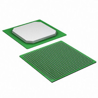
IC STRATIX FPGA 25K LE 672-BGA
Manufacturer
Altera
Series
Stratix®r
Datasheet
1.EP1S10F780C7.pdf
(276 pages)
Specifications of EP1S25B672C7N
Number Of Logic Elements/cells
25660
Number Of Labs/clbs
2566
Total Ram Bits
1944576
Number Of I /o
473
Voltage - Supply
1.425 V ~ 1.575 V
Mounting Type
Surface Mount
Operating Temperature
0°C ~ 85°C
Package / Case
672-BGA
Lead Free Status / RoHS Status
Lead free / RoHS Compliant
Number Of Gates
-
Available stocks
Company
Part Number
Manufacturer
Quantity
Price


Timing Model
4–22
Stratix Device Handbook, Volume 1
Internal Timing Parameters
Internal timing parameters are specified on a speed grade basis
independent of device density.
Stratix device internal timing microparameters for LEs, IOEs, TriMatrix
memory structures, DSP blocks, and MultiTrack interconnects.
t
t
t
t
t
t
t
t
t
t
t
t
t
t
t
t
t
t
t
SU
H
CO
LUT
CLR
PRE
CLKHL
SU_R
SU_C
H
CO_R
C O _ C
PIN2COMBOUT_R
PIN2COMBOUT_C
COMBIN2PIN_R
COMBIN2PIN_C
CLR
PRE
CLKHL
Table 4–37. LE Internal Timing Microparameter Descriptions
Table 4–38. IOE Internal Timing Microparameter Descriptions
Symbol
Symbol
LE register setup time before clock
LE register hold time after clock
LE register clock-to-output delay
LE combinatorial LUT delay for data-in to data-out
Minimum clear pulse width
Minimum preset pulse width
Register minimum clock high or low time. The maximum core
clock frequency can be calculated by 1/(2 × t
Row IOE input register setup time
Column IOE input register setup time
IOE input and output register hold time after clock
Row IOE input and output register clock-to-output delay
Column IOE input and output register clock-to-output delay
Row input pin to IOE combinatorial output
Column input pin to IOE combinatorial output
Row IOE data input to combinatorial output pin
Column IOE data input to combinatorial output pin
Minimum clear pulse width
Minimum preset pulse width
Register minimum clock high or low time. The maximum I/O
clock frequency can be calculated by 1/(2 × t
Performance may also be affected by I/O timing, use of PLL,
and I/O programmable settings.
Tables 4–37
Parameter
Parameter
through
4–42
Altera Corporation
describe the
CLKHL
CLKHL
January 2006
).
).
™
Related parts for EP1S25B672C7N
Image
Part Number
Description
Manufacturer
Datasheet
Request
R

Part Number:
Description:
CYCLONE II STARTER KIT EP2C20N
Manufacturer:
Altera
Datasheet:


Part Number:
Description:
CPLD, EP610 Family, ECMOS Process, 300 Gates, 16 Macro Cells, 16 Reg., 16 User I/Os, 5V Supply, 35 Speed Grade, 24DIP
Manufacturer:
Altera Corporation
Datasheet:
Part Number:
Description:
CPLD, EP610 Family, ECMOS Process, 300 Gates, 16 Macro Cells, 16 Reg., 16 User I/Os, 5V Supply, 15 Speed Grade, 24DIP
Manufacturer:
Altera Corporation
Datasheet:
Part Number:
Description:
Manufacturer:
Altera Corporation
Datasheet:
Part Number:
Description:
CPLD, EP610 Family, ECMOS Process, 300 Gates, 16 Macro Cells, 16 Reg., 16 User I/Os, 5V Supply, 30 Speed Grade, 24DIP
Manufacturer:
Altera Corporation
Datasheet:
Part Number:
Description:
High-performance, low-power erasable programmable logic devices with 8 macrocells, 10ns
Manufacturer:
Altera Corporation
Datasheet:
Part Number:
Description:
High-performance, low-power erasable programmable logic devices with 8 macrocells, 7ns
Manufacturer:
Altera Corporation
Datasheet:
Part Number:
Description:
Classic EPLD
Manufacturer:
Altera Corporation
Datasheet:
Part Number:
Description:
High-performance, low-power erasable programmable logic devices with 8 macrocells, 10ns
Manufacturer:
Altera Corporation
Datasheet:
Part Number:
Description:
Manufacturer:
Altera Corporation
Datasheet:
Part Number:
Description:
Manufacturer:
Altera Corporation
Datasheet:
Part Number:
Description:
Manufacturer:
Altera Corporation
Datasheet:
Part Number:
Description:
CPLD, EP610 Family, ECMOS Process, 300 Gates, 16 Macro Cells, 16 Reg., 16 User I/Os, 5V Supply, 25 Speed Grade, 24DIP
Manufacturer:
Altera Corporation
Datasheet: