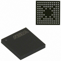
EPM240GM100C5N Altera, EPM240GM100C5N Datasheet - Page 7

EPM240GM100C5N
Manufacturer Part Number
EPM240GM100C5N
Description
IC MAX II CPLD 240 LE 100-MBGA
Manufacturer
Altera
Series
MAX® IIr
Datasheets
1.EPM240GT100C5N.pdf
(6 pages)
2.EPM240GT100C5N.pdf
(88 pages)
3.EPM240GM100C5N.pdf
(10 pages)
Specifications of EPM240GM100C5N
Programmable Type
In System Programmable
Delay Time Tpd(1) Max
4.7ns
Voltage Supply - Internal
1.71 V ~ 1.89 V
Number Of Logic Elements/blocks
240
Number Of Macrocells
192
Number Of I /o
80
Operating Temperature
0°C ~ 85°C
Mounting Type
Surface Mount
Package / Case
100-MBGA
Voltage
1.8V
Memory Type
FLASH
Number Of Logic Elements/cells
240
Family Name
MAX II
# Macrocells
192
Frequency (max)
1.8797GHz
Propagation Delay Time
7.5ns
Number Of Logic Blocks/elements
24
# I/os (max)
80
Operating Supply Voltage (typ)
1.8V
In System Programmable
Yes
Operating Supply Voltage (min)
1.71V
Operating Supply Voltage (max)
1.89V
Operating Temp Range
0C to 85C
Operating Temperature Classification
Commercial
Mounting
Surface Mount
Pin Count
100
Package Type
MBGA
Lead Free Status / RoHS Status
Lead free / RoHS Compliant
Features
-
Lead Free Status / Rohs Status
Compliant
Other names
544-1726
Available stocks
Company
Part Number
Manufacturer
Quantity
Price
Company:
Part Number:
EPM240GM100C5N
Manufacturer:
CYPESS
Quantity:
1
Company:
Part Number:
EPM240GM100C5N
Manufacturer:
ALTERA10
Quantity:
1 287
Part Number:
EPM240GM100C5N
Manufacturer:
ALTERA/阿尔特拉
Quantity:
20 000
Altera Corporation
1
144-Pin TQFP Package TCK JTAG Input Glitching
The EPM1270 ES device in the 144-pin TQFP package can exhibit a high
pulse glitch on the TCK input as a result of coupling from the adjacent TDO
output pin. This can lead to double clocking and failed boundary scan
and in-system programming operations. The TCK input is susceptible to
high pulse glitches when its input signal fall time is greater than 50 ns for
3.3-V or 2.5-V V
V
by pin 4 of the 10-pin header. This affects the voltage level of TCK driving
the MAX II device. See the respective Altera download cable data sheet
for more information.
This issue can be avoided by ensuring that the download cable or third-
party programming/JTAG hardware supplies a TCK fall time less than
50 ns when driving the combined load capacitance of the cable, JTAG
header, and trace for TCK.
Table 4
cables with no load. All the cables shown exhibit fall times less than 50 ns
for no load conditions.
If using third-party tool hardware or if excessive loading on TCK does not
meet the 50 ns fall time requirement for EPM1270 ES devices, Altera
recommends that you add a buffer device with sufficient edge rates to
buffer TCK, TDI, and TMS near the EPM1270 ES device.
1
Notes to
(1)
(2)
(3)
USB Blaster
Byteblaster™ II Cable
ByteblasterMV™ Cable
MasterBlaster™ Cable
Table 4. Altera Download Cable TCK Fall Times
CCIO
Altera Download Cable
Numbers are approximate and do not represent specifications.
This is the edge rate at the cable edge connector before driving the load of the
board JTAG header and board trace.
These cables do not support 2.5-V operation.
(V
shows the approximate TCK fall times of the Altera download
CCIO1
Table
Production devices do not exhibit this input glitch for slow input
fall times greater than 1 µs.
Production devices do not exhibit this TCK glitch.
). The I/O voltage for Altera download cables is determined
4:
CCIO
. The JTAG pin I/O voltage is controlled by the bank 1
3.3-V Fall Times
12
25
15
2
EPM1270 ES Device Issues
Notes
2.5-V Fall Times
(1),
(2)
20
(3)
(3)
7
Preliminary
7


