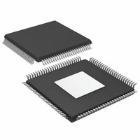
AD9779BSVZ Analog Devices Inc, AD9779BSVZ Datasheet - Page 2

AD9779BSVZ
Manufacturer Part Number
AD9779BSVZ
Description
IC DAC 16BIT DUAL 1GSPS 100TQFP
Manufacturer
Analog Devices Inc
Datasheet
1.AD9776BSVZRL.pdf
(56 pages)
Specifications of AD9779BSVZ
Data Interface
Serial
Number Of Bits
16
Number Of Converters
2
Voltage Supply Source
Analog and Digital
Power Dissipation (max)
300mW
Operating Temperature
-40°C ~ 85°C
Mounting Type
Surface Mount
Package / Case
100-TQFP Exposed Pad, 100-eTQFP, 100-HTQFP, 100-VQFP
Resolution (bits)
16bit
Sampling Rate
1GSPS
Input Channel Type
Parallel
Digital Ic Case Style
QFP
No. Of Pins
160
Operating Temperature Range
-40°C To +85°C
Lead Free Status / RoHS Status
Lead free / RoHS Compliant
For Use With
AD9779A-EBZ - BOARD EVALUATION FOR AD9779A
Settling Time
-
Lead Free Status / RoHS Status
Lead free / RoHS Compliant, Lead free / RoHS Compliant
Available stocks
Company
Part Number
Manufacturer
Quantity
Price
Company:
Part Number:
AD9779BSVZ
Manufacturer:
AD
Quantity:
2 100
Company:
Part Number:
AD9779BSVZ
Manufacturer:
ADI
Quantity:
325
Company:
Part Number:
AD9779BSVZ
Manufacturer:
Analog Devices Inc
Quantity:
10 000
Part Number:
AD9779BSVZ
Manufacturer:
ADI/亚德诺
Quantity:
20 000
Company:
Part Number:
AD9779BSVZRL
Manufacturer:
Analog Devices Inc
Quantity:
10 000
AD9776/AD9778/AD9779
TABLE OF CONTENTS
Features .............................................................................................. 1
Applications....................................................................................... 1
General Description ......................................................................... 1
Product Highlights ........................................................................... 1
Typical Signal Chain......................................................................... 1
Revision History ............................................................................... 2
Functional Block Diagram .............................................................. 3
Specifications..................................................................................... 4
Absolute Maximum Ratings............................................................ 8
Pin Configurations and Function Descriptions ........................... 9
Typical Performance Characteristics ........................................... 15
Terminology .................................................................................... 24
Theory of Operation ...................................................................... 25
REVISION HISTORY
3/07—Rev. 0 to Rev. A
Changes to Features.......................................................................... 1
Changes to Applications .................................................................. 1
Changes to General Product Highlights........................................ 1
Added Figure 1, Renumbered Figures Sequentially..................... 1
Changes to Table 1............................................................................ 4
Changes to Table 2............................................................................ 5
Changes to Table 3............................................................................ 5
Changes to Figure 53 and Figure 54............................................. 26
Changes to Table 12........................................................................ 29
Changes to Power Dissipation Section ........................................ 39
DC Specifications ......................................................................... 4
Digital Specifications ................................................................... 6
Digital Input Data Timing Specifications ................................. 7
AC Specifications.......................................................................... 7
Thermal Resistance ...................................................................... 8
ESD Caution.................................................................................. 8
Serial Peripheral Interface ......................................................... 25
MSB/LSB Transfers..................................................................... 26
Rev. A | Page 2 of 56
SPI Register Map ............................................................................ 27
Interpolation Filter Architecture .................................................. 31
Evaluation Board Operation ......................................................... 46
Outline Dimensions ....................................................................... 56
Added Table 19, Renumbered Tables Sequentially .................... 41
Changes to Figure 92 and Figure 93............................................. 42
Changes to Figure 94...................................................................... 42
Added New Figure 95, Renumbered Figures Sequentially ....... 42
Changes to Synchronization of Input Data to the REFCLK Input
(Pin 5 and Pin 6) with PLL Enabled or Disabled Section ......... 43
Added New Figure 96, Renumbered Figures Sequentially ....... 43
Changes to Figure 106 ................................................................... 51
7/05—Revision 0: Initial Version
Interpolation Filter Minimum and Maximum Bandwidth
Specifications .............................................................................. 35
Driving the REFCLK Input....................................................... 35
Internal PLL Clock Multiplier/Clock Distribution................ 36
Full-Scale Current Generation ................................................. 38
Power Dissipation....................................................................... 39
Power-Down and Sleep Modes................................................. 41
Interleaved Data Mode .............................................................. 41
Timing Information ................................................................... 41
Synchronization of Input Data to DATACLK
Output (Pin 37)........................................................................... 43
Synchronization of Input Data to the REFCLK Input (Pin 5
and Pin 6) with PLL Enabled or Disabled............................... 43
Modifying the Evaluation Board to Use the AD8349 On-
Board Quadrature Modulator................................................... 48
Evaluation Board Schematics ................................................... 49
Ordering Guide .......................................................................... 56


