DAC8413FPC Analog Devices Inc, DAC8413FPC Datasheet - Page 5
DAC8413FPC
Manufacturer Part Number
DAC8413FPC
Description
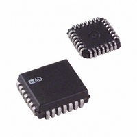
IC DAC 12BIT QUAD READBK 28-PLCC
Manufacturer
Analog Devices Inc
Datasheet
1.DAC8412FPCZ.pdf
(20 pages)
Specifications of DAC8413FPC
Rohs Status
RoHS non-compliant
Settling Time
6µs
Number Of Bits
12
Data Interface
Parallel
Number Of Converters
4
Voltage Supply Source
Single Supply
Power Dissipation (max)
330mW
Operating Temperature
-40°C ~ 85°C
Mounting Type
Surface Mount
Package / Case
28-LCC (J-Lead)
Number Of Channels
4
Resolution
12b
Conversion Rate
167KSPS
Interface Type
Parallel
Single Supply Voltage (typ)
5V
Dual Supply Voltage (typ)
±15V
Architecture
R-2R
Power Supply Requirement
Single/Dual
Output Type
Voltage
Integral Nonlinearity Error
±4LSB
Single Supply Voltage (min)
4.75V
Single Supply Voltage (max)
5.25V
Dual Supply Voltage (min)
±14.25V
Dual Supply Voltage (max)
±15.75V
Operating Temp Range
-40C to 85C
Operating Temperature Classification
Industrial
Mounting
Surface Mount
Pin Count
28
Package Type
PLCC
Lead Free Status / Rohs Status
Not Compliant
Available stocks
Company
Part Number
Manufacturer
Quantity
Price
Company:

Part Number:
DAC8413FPC
Manufacturer:
VISHAY
Quantity:
6 652
Company:
Part Number:
DAC8413FPC
Manufacturer:
Analog Devices Inc
Quantity:
10 000
Part Number:
DAC8413FPC
Manufacturer:
ADI/亚德诺
Quantity:
20 000
Company:
Part Number:
DAC8413FPC-REEL
Manufacturer:
Analog Devices Inc
Quantity:
10 000
Company:
Part Number:
DAC8413FPCZ
Manufacturer:
Analog Devices Inc
Quantity:
10 000
Company:
Part Number:
DAC8413FPCZ-REEL
Manufacturer:
Analog Devices Inc
Quantity:
10 000


Parameter
SUPPLY CHARACTERISTICS
1
2
3
4
5
All supplies can be varied ±5%, and operation is guaranteed. Device is tested with V
For single-supply operation only (V
Operation is guaranteed over this reference range, but linearity is neither tested nor guaranteed.
All parameters are guaranteed by design.
All input control signals are specified with tr = tf = 5 ns (10% to 90% of 5 V) and timed from a voltage level of 1.6 V.
Write Data Setup
Write Data Hold
Load Data Pulse Width
Reset Pulse Width
Chip Select Read Pulse Width
Read Data Hold
Read Data Setup
Data to High-Z
Chip Select to Data
Power Supply Sensitivity
Positive Supply Current
Negative Supply Current
Power Dissipation
A0/A1
DATA
OUT
R/W
CS
t
RCS
Figure 3. Data Output (Read Timing)
HIGH-Z
t
CSD
t
AS
DATA VALID
t
REFL
RDS
= 0.0 V, V
t
t
AH
RDH
SS
= 0.0 V). Due to internal offset errors, INL and DNL are measured beginning at 0x005.
t
HIGH-Z
DZ
Symbol
t
t
t
t
t
t
t
t
t
PSS
I
I
P
DD
SS
WDS
WDH
LDW
RESET
RCS
RDH
RDS
DZ
CSD
DISS
Conditions
t
t
t
t
C
C
V
V
V
Rev. F | Page 5 of 20
WCS
WCS
RCS
RCS
L
L
SS
SS
SS
= 10 pF
= 100 pF
= −5.0 V
= 0 V
= −5.0 V
= 170 ns
= 170 ns
= 150 ns
= 150 ns
DD
= 4.75 V.
DATA IN
RESET
A0/A1
LDAC
R/W
Figure 4. Data Write (Input and Output Registers) Timing
CS
t
WDS
t
t
WS
t
AS
LS
t
RESET
Min
20
0
180
150
170
20
0
−10
t
WCS
DAC8412/DAC8413
Typ
100
7
60
110
t
t
WH
AH
t
LH
Max
200
320
12
t
WDH
t
LDW
Units
ns
ns
ns
ns
ns
ns
ns
ns
ns
ppm/V
mA
mA
mW
mW
Related parts for DAC8413FPC
Image
Part Number
Description
Manufacturer
Datasheet
Request
R

Part Number:
Description:
Analog Standard Cell 8-Bit Digital to Analog Converter
Manufacturer:
AMSCO [austriamicrosystems AG]
Datasheet:

Part Number:
Description:
±1.7g Dual-Axis IMEMS Accelerometer Evaluation Board
Manufacturer:
Analog Devices Inc
Datasheet:

Part Number:
Description:
Inertial Sensor Evaluation System
Manufacturer:
Analog Devices Inc
Datasheet:
Part Number:
Description:
Manufacturer:
Analog Devices Inc
Datasheet:
Part Number:
Description:
Manufacturer:
Analog Devices Inc
Datasheet:
Part Number:
Description:
Manufacturer:
Analog Devices Inc
Datasheet:
Part Number:
Description:
Manufacturer:
Analog Devices Inc
Datasheet:
Part Number:
Description:
Manufacturer:
Analog Devices Inc
Datasheet:
Part Number:
Description:
Manufacturer:
Analog Devices Inc
Datasheet:
Part Number:
Description:
Manufacturer:
Analog Devices Inc
Datasheet:
Part Number:
Description:
Manufacturer:
Analog Devices Inc
Datasheet:
Part Number:
Description:
Manufacturer:
Analog Devices Inc
Datasheet:
Part Number:
Description:
Manufacturer:
Analog Devices Inc
Datasheet: