DAC8413FPC Analog Devices Inc, DAC8413FPC Datasheet - Page 15
DAC8413FPC
Manufacturer Part Number
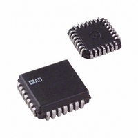
DAC8413FPC
Description
IC DAC 12BIT QUAD READBK 28-PLCC
Manufacturer
Analog Devices Inc
Datasheet
1.DAC8412FPCZ.pdf
(20 pages)
Specifications of DAC8413FPC
Rohs Status
RoHS non-compliant
Settling Time
6µs
Number Of Bits
12
Data Interface
Parallel
Number Of Converters
4
Voltage Supply Source
Single Supply
Power Dissipation (max)
330mW
Operating Temperature
-40°C ~ 85°C
Mounting Type
Surface Mount
Package / Case
28-LCC (J-Lead)
Number Of Channels
4
Resolution
12b
Conversion Rate
167KSPS
Interface Type
Parallel
Single Supply Voltage (typ)
5V
Dual Supply Voltage (typ)
±15V
Architecture
R-2R
Power Supply Requirement
Single/Dual
Output Type
Voltage
Integral Nonlinearity Error
±4LSB
Single Supply Voltage (min)
4.75V
Single Supply Voltage (max)
5.25V
Dual Supply Voltage (min)
±14.25V
Dual Supply Voltage (max)
±15.75V
Operating Temp Range
-40C to 85C
Operating Temperature Classification
Industrial
Mounting
Surface Mount
Pin Count
28
Package Type
PLCC
Lead Free Status / Rohs Status
Not Compliant
Available stocks
Company
Part Number
Manufacturer
Quantity
Price
Company:

Part Number:
DAC8413FPC
Manufacturer:
VISHAY
Quantity:
6 652
Company:
Part Number:
DAC8413FPC
Manufacturer:
Analog Devices Inc
Quantity:
10 000
Part Number:
DAC8413FPC
Manufacturer:
ADI/亚德诺
Quantity:
20 000
Company:
Part Number:
DAC8413FPC-REEL
Manufacturer:
Analog Devices Inc
Quantity:
10 000
Company:
Part Number:
DAC8413FPCZ
Manufacturer:
Analog Devices Inc
Quantity:
10 000
Company:
Part Number:
DAC8413FPCZ-REEL
Manufacturer:
Analog Devices Inc
Quantity:
10 000


RESET
The RESET function can be used either at power-up or at any
time during DAC operation. The RESET function is independent
of CS . This pin is active low and sets the DAC output registers
to either center code for the DAC8412, or zero code for the
DAC8413. The reset-to-center code is most useful when the
DAC is configured for bipolar references and an output of 0 V
after reset is desired.
SUPPLIES
Supplies required are V
be set between −15 V and 0 V. V
operating range is between 5 V and 15 V.
Table 6. DAC8412/DAC8413 Logic Table
A1
L
L
H
H
L
L
H
H
L
L
H
H
X
X
X
X
1
DAC8412 resets to midscale, and DAC8413 resets to zero scale. L = logic low; H = logic high; X = don’t care. Input and output registers are transparent when asserted.
A0
L
H
L
H
L
H
L
H
L
H
L
H
X
X
X
X
R/W
L
L
L
L
L
L
L
L
H
H
H
H
X
X
X
X
SS
, V
CS
L
L
L
L
L
L
L
L
L
L
L
L
H
H
X
H
DD
, and V
RS
H
H
H
H
H
H
H
H
H
H
H
H
H
H
L
DD
is the positive supply; its
LOGIC
LDAC
L
L
L
L
H
H
H
H
H
H
H
H
L
H
X
X
. The V
SS
supply can
Input Register
Write
Write
Write
Write
Write
Write
Write
Write
Read
Read
Read
Read
Hold
Hold
All registers latched to midscale/zero-scale
All registers reset to midscale/zero-scale
Rev. F | Page 15 of 20
V
function. It is normally connected to +5 V. This pin is a logic
reference input only. It does not supply current to the device. If
the readback function is not being used, V
circuit. While V
does supply currents to the digital outputs when readback is used.
AMPLIFIERS
Unlike many voltage output DACs, the DAC8412 features buffered
voltage outputs. Each output is capable of both sourcing and
sinking 5 mA at ±10 V, eliminating the need for external
amplifiers when driving 500 pF or smaller capacitive load in
most applications. These amplifiers are short-circuit protected.
Output Register
Write
Write
Write
Write
Hold
Hold
Hold
Hold
Hold
Hold
Hold
Hold
Update all output registers
Hold
LOGIC
is the digital output supply voltage for the readback
LOGIC
does not supply current to the DAC8412, it
1
1
DAC8412/DAC8413
Mode
Transparent
Transparent
Transparent
Transparent
Write input
Write input
Write input
Write input
Read input
Read input
Read input
Read input
Hold
LOGIC
can be left open-
DAC
A
B
C
D
A
B
C
D
A
B
C
D
All
All
All
All
Related parts for DAC8413FPC
Image
Part Number
Description
Manufacturer
Datasheet
Request
R

Part Number:
Description:
Analog Standard Cell 8-Bit Digital to Analog Converter
Manufacturer:
AMSCO [austriamicrosystems AG]
Datasheet:

Part Number:
Description:
±1.7g Dual-Axis IMEMS Accelerometer Evaluation Board
Manufacturer:
Analog Devices Inc
Datasheet:

Part Number:
Description:
Inertial Sensor Evaluation System
Manufacturer:
Analog Devices Inc
Datasheet:
Part Number:
Description:
Manufacturer:
Analog Devices Inc
Datasheet:
Part Number:
Description:
Manufacturer:
Analog Devices Inc
Datasheet:
Part Number:
Description:
Manufacturer:
Analog Devices Inc
Datasheet:
Part Number:
Description:
Manufacturer:
Analog Devices Inc
Datasheet:
Part Number:
Description:
Manufacturer:
Analog Devices Inc
Datasheet:
Part Number:
Description:
Manufacturer:
Analog Devices Inc
Datasheet:
Part Number:
Description:
Manufacturer:
Analog Devices Inc
Datasheet:
Part Number:
Description:
Manufacturer:
Analog Devices Inc
Datasheet:
Part Number:
Description:
Manufacturer:
Analog Devices Inc
Datasheet:
Part Number:
Description:
Manufacturer:
Analog Devices Inc
Datasheet: