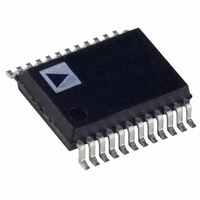
AD7840ARS Analog Devices Inc, AD7840ARS Datasheet

AD7840ARS
Specifications of AD7840ARS
Available stocks
Related parts for AD7840ARS
AD7840ARS Summary of contents
Page 1
FEATURES Complete 14-Bit Voltage Output DAC Parallel and Serial Interface Capability 80 dB Signal-to-Noise Ratio Interfaces to High Speed DSP Processors e.g., ADSP-2100, TMS32010, TMS32020 45 ns min WR Pulse Width Low Power – typ. Operates from ...
Page 2
AD7840–SPECIFICATIONS Parameter 2 DYNAMIC PERFORMANCE 3 Signal to Noise Ratio (SNR) Total Harmonic Distortion (THD) –78 Peak Harmonic or Spurious Noise –78 DC ACCURACY Resolution Integral Nonlinearity Differential Nonlinearity Bipolar Zero Error 5 Positive Full Scale Error 5 Negative Full ...
Page 3
... DD AD7840JN DD AD7840KN + 0 AD7840JP + 0 AD7840KP AD7840AQ AD7840ARS AD7840BQ 3 AD7840SQ NOTES 1 To order MIL-STD-883, Class B processed parts, add /883B to part number. Contact your local sales office for military data sheet and availability Plastic DIP Plastic Leaded Chip Carrier Cerdip. 3 This grade will be available to /883B processing only. ...
Page 4
AD7840 DIP Pin Pin No. Mnemonic Function 1 CS/SERIAL Chip Select/Serial Input. When driven with normal logic levels active low logic input which is used in conjunction with WR to load parallel data to the input latch. ...
Page 5
DIP/SSOP D/A SECTION The AD7840 contains a 14-bit voltage mode D/A converter consisting of highly stable thin film resistors and high speed NMOS single-pole, double-throw switches. The simplified cir- cuit diagram for the DAC section is shown in Figure 1. ...
Page 6
AD7840 OP AMP SECTION The output from the voltage mode DAC is buffered by a noninverting amplifier. Internal scaling resistors on the AD7840 configure an output voltage range for an input reference voltage The ...
Page 7
Table III. Parallel Mode Truth Table CS WR LDAC Function Both Latches Latched Input Latch Transparent Input Latch Latched } DAC Latch Transparent X ...
Page 8
AD7840 As in the parallel mode, the LDAC signal controls the loading of data to the DAC latch. Normally, data is loaded to the DAC latch on the falling edge of LDAC. However, if LDAC is held low, then serial ...
Page 9
Figure 11. AD7840 Dynamic Performance Test Circuit The digitizer sampling is synchronized with the AD7840 update rate to ease FFT calculations. The digitizer samples the AD7840 after the output has settled to its new value. Therefore, if the digitizer was ...
Page 10
AD7840 MICROPROCESSOR INTERFACING The AD7840 logic architecture allows two interfacing options for interfacing the part to microprocessor systems. It offers a 14-bit wide parallel format and a serial format. Fast pulse widths and data setup times allow the AD7840 to ...
Page 11
AD7840–68000 Interface An interface between the AD7840 and the 68000 microproces- sor is shown in Figure 19. In this interface example, the LDAC input is hardwired low result the DAC latch and analog output are updated on the ...
Page 12
AD7840 AD7840–TMS32020 Serial Interface Figure 22 shows a serial interface between the AD7840 and the TMS32020 DSP processor. In this interface, the CLKX and FSX pin of the TMS32020 are generated from the clock/timer circuitry. The same clock/timer circuitry generates ...
Page 13
DATA ACQUISITION BOARD Figure 25 shows the AD7840 in a data acquisition circuit. The corresponding printed circuit board (PCB) layout and silkscreen are shown in Figures 26 to 28. The board layout has three inter- face ports: one serial and ...
Page 14
AD7840 Figure 25. Data Acquisition Circuit Using the AD7840 Figure 26. PCB Silkscreen for Figure 25 –14– REV. B ...
Page 15
Figure 27. PCB Component Side Layout for Figure 25 REV. B Figure 28. PCB Solder Side Layout for Figure 25 –15– AD7840 ...
Page 16
AD7840 Figure 29. SKT4, IDC Connector Pinout Figure 30. SKT5, D-Type Connector Pinout OUTLINE DIMENSIONS Dimensions shown in inches and (mm). Plastic DIP (N-24) Ceramic DIP (D-24A) Cerdip (Q-24) PLCC (P-28A) –16– REV. B ...


