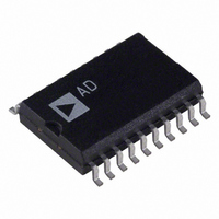
DAC312HS Analog Devices Inc, DAC312HS Datasheet - Page 12

DAC312HS
Manufacturer Part Number
DAC312HS
Description
IC DAC 12BIT MULTIPLY HS 20-SOIC
Manufacturer
Analog Devices Inc
Datasheet
1.DAC312HPZ.pdf
(14 pages)
Specifications of DAC312HS
Mounting Type
Surface Mount
Package / Case
20-SOIC (7.5mm Width)
Rohs Status
RoHS non-compliant
Settling Time
250ns
Number Of Bits
12
Data Interface
Parallel
Number Of Converters
1
Voltage Supply Source
Dual ±
Power Dissipation (max)
375mW
Operating Temperature
-40°C ~ 85°C
Resolution (bits)
12bit
No. Of Pins
20
Peak Reflow Compatible (260 C)
No
No. Of Bits
12 Bit
Leaded Process Compatible
No
Interface Type
Serial
Lead Free Status / RoHS Status
Contains lead / RoHS non-compliant
Available stocks
Company
Part Number
Manufacturer
Quantity
Price
Part Number:
DAC312HS-REEL
Manufacturer:
ADI/亚德诺
Quantity:
20 000
Company:
Part Number:
DAC312HSREEL
Manufacturer:
TOSHIBA
Quantity:
4 082
Part Number:
DAC312HSZ
Manufacturer:
ADI/亚德诺
Quantity:
20 000
Part Number:
DAC312HSZ-REEL
Manufacturer:
ADI/亚德诺
Quantity:
20 000
DAC312
DIFFERENTIAL VS. INTEGRAL NONLINEARITY
Integral nonlinearity, for the purposes of the discussion, refers
to the “straightness”of the line drawn through the individual re-
sponse points of a data converter. Differential nonlinearity, on
the other hand, refers to the deviation of the spacing of the adja-
cent points from a 1 LSB ideal spacing. Both may be expressed
as either a percentage of full-scale output or as fractional LSBs
or both. The following figures define the manner in which these
parameters are specified. The left figure shows a portion of the
transfer curve of a DAC with 1/2 LSB INL and the (implied)
DNL spec of 1 LSB. Below this is a graphic representation of
the way this would appear on a CRT, for example, if the D/A
converter output were to be applied to the Y input of a CRT as
shown in the application schematic titled “CRT Display Drive.”
On the right is a portion of the transfer curve of a DAC speci-
fied for 2 LSB INL with 1/2 LSB DNL specified and the
graphic display below it.
DIFFERENTIAL LINEARITY COMPARISON
D/A Converter with 1/2 LSB INL, 1 LSB DNL
ENLARGED “POSITIONAL” OUTPUTS
Video Deflection by DACs
–12–
One of the characteristics of an R-2R DAC in standard form is
that any transition which causes a zero LSB change (i.e., the
same output for two different codes) will exhibit the same out-
put each time that transition occurs. The same holds true for
transitions causing a 2 LSB change. These two problem transi-
tions are allowable for the standard definition of monotonicity
and also allow the device to be specified very tightly for INL.
The major problem arising from this error type is in A/D con-
verter implementations. Inputs producing the same output are
now represented by ambiguous output codes for an identical in-
put. Also, 2 LSB gaps can cause large errors at those input lev-
els (assuming 1/2 LSB quantizing levels). It can be seen from
the two figures that the DNL specified D/A converter will yield
much finer grained data than the INL specified part, thus im-
proving the ability of the A/D to resolve changes in the analog
input.
D/A Converter with 2 LSB INL, 1/2 LSB DNL
ENLARGED “POSITIONAL” OUTPUTS
Video Deflection by DACs
REV. C


