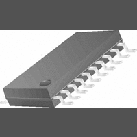
CS4351-DZZ Cirrus Logic Inc, CS4351-DZZ Datasheet - Page 2

CS4351-DZZ
Manufacturer Part Number
CS4351-DZZ
Description
IC DAC STER 112DB 192KHZ 20TSSOP
Manufacturer
Cirrus Logic Inc
Datasheet
1.CS4351-CZZ.pdf
(37 pages)
Specifications of CS4351-DZZ
Data Interface
Serial
Number Of Bits
24
Number Of Converters
2
Voltage Supply Source
Analog and Digital
Power Dissipation (max)
354mW
Operating Temperature
-40°C ~ 85°C
Mounting Type
Surface Mount
Package / Case
20-TSSOP
Resolution (bits)
24bit
Sampling Rate
192kSPS
Input Channel Type
Serial
Supply Current
15mA
Digital Ic Case Style
TSSOP
No. Of Pins
20
Lead Free Status / RoHS Status
Lead free / RoHS Compliant
For Use With
598-1152 - BOARD EVAL FOR CS4351 DAC
Settling Time
-
Lead Free Status / RoHS Status
Lead free / RoHS Compliant, Lead free / RoHS Compliant
Available stocks
Company
Part Number
Manufacturer
Quantity
Price
Company:
Part Number:
CS4351-DZZR
Manufacturer:
CIRRUSLOGIC
Quantity:
2 549
2
TABLE OF CONTENTS
1. PIN DESCRIPTION ............................................................................................................................... 5
2. CHARACTERISTICS AND SPECIFICATIONS ..................................................................................... 6
3. TYPICAL CONNECTION DIAGRAM .................................................................................................. 14
4. APPLICATIONS .................................................................................................................................. 15
5. REGISTER QUICK REFERENCE ....................................................................................................... 23
6. REGISTER DESCRIPTION ................................................................................................................. 24
SPECIFIED OPERATING CONDITIONS .............................................................................................. 6
ABSOLUTE MAXIMUM RATINGS ........................................................................................................ 6
DAC ANALOG CHARACTERISTICS .................................................................................................... 7
COMBINED INTERPOLATION & ON-CHIP ANALOG FILTER RESPONSE ....................................... 8
COMBINED INTERPOLATION & ON-CHIP ANALOG FILTER RESPONSE ....................................... 9
SWITCHING SPECIFICATIONS - SERIAL AUDIO INTERFACE ...................................................... 10
SWITCHING CHARACTERISTICS - CONTROL PORT - I²C
SWITCHING CHARACTERISTICS - CONTROL PORT - SPI™ FORMAT......................................... 12
DIGITAL CHARACTERISTICS............................................................................................................ 13
POWER AND THERMAL CHARACTERISTICS ................................................................................. 13
4.1 Sample Rate Range/Operational Mode Detect ............................................................................ 15
4.2 System Clocking ........................................................................................................................... 15
4.3 Digital Interface Format ................................................................................................................ 16
4.4 De-Emphasis Control ................................................................................................................... 17
4.5 Recommended Power-Up Sequence ........................................................................................... 18
4.6 Popguard
4.7 Mute Control ................................................................................................................................. 19
4.8 Grounding and Power Supply Arrangements ............................................................................... 19
4.9 Control Port Interface ................................................................................................................... 20
4.10 Memory Address Pointer (MAP) ................................................................................................. 22
6.1 Chip ID - Register 01h .................................................................................................................. 24
6.2 Mode Control 1 - Register 02h ..................................................................................................... 24
6.3 Volume Mixing and Inversion Control - Register 03h ................................................................... 25
4.1.1 Auto-Detect Enabled ........................................................................................................ 15
4.1.2 Auto-Detect Disabled ....................................................................................................... 15
4.3.1 Stand-Alone Mode ........................................................................................................... 16
4.3.2 Control Port Mode ........................................................................................................... 16
4.4.1 Stand-Alone Mode ........................................................................................................... 18
4.4.2 Control Port Mode ............................................................................................................ 18
4.5.1 Stand-Alone Mode ........................................................................................................... 18
4.5.2 Control Port Mode ............................................................................................................ 18
4.6.1 Power-Up ......................................................................................................................... 18
4.6.2 Power-Down .................................................................................................................... 19
4.6.3 Discharge Time ................................................................................................................ 19
4.8.1 Capacitor Placement ........................................................................................................ 19
4.9.1 MAP Auto Increment ........................................................................................................ 20
4.9.2 I²C Mode .......................................................................................................................... 20
4.9.3 SPI Mode ......................................................................................................................... 21
4.10.1 INCR (Auto Map Increment Enable) .............................................................................. 22
4.10.2 MAP (Memory Address Pointer) .................................................................................... 22
6.2.1 Digital Interface Format (DIF2:0) Bits 6-4 ........................................................................ 24
6.2.2 De-Emphasis Control (DEM1:0) Bits 3-2. ........................................................................ 24
6.2.3 Functional Mode (FM) Bits 1-0 ......................................................................................... 25
6.3.1 Channel A Volume = Channel B Volume (VOLB=A) Bit 7 ............................................... 25
6.3.2 Invert Signal Polarity (Invert_A) Bit 6 ............................................................................... 25
6.3.3 Invert Signal Polarity (Invert_B) Bit 5 ............................................................................... 25
®
Transient Control ....................................................................................................... 18
®
FORMAT ........................................... 11
CS4351
DS566F1


