U0805R104KCT MULTICOMP, U0805R104KCT Datasheet - Page 7
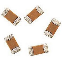
U0805R104KCT
Manufacturer Part Number
U0805R104KCT
Description
CAPACITOR CERAMIC, 0.1UF, 50V, X7R, 0805
Manufacturer
MULTICOMP
Datasheet
1.MCCA000432.pdf
(19 pages)
Specifications of U0805R104KCT
Dielectric Characteristic
X7R
Capacitance
0.1µF
Capacitance Tolerance
± 10%
Voltage Rating
50VDC
Capacitor Case Style
0805
No. Of Pins
2
Capacitor Mounting
SMD
Rohs Compliant
Yes


Temperature
Vibration
Deflection
Nickel Barrier
Multilayer Ceramic Capacitors
Cycle
Item
Capacitance
Capacitance
Capacitance
Appearance
Appearance
Appearance
External
DF or Q
External
Bending
Strength
External
Change
Change
Change
(∆ C/C)
(∆ C/C)
(∆ C/C)
DF
IR
X7R, X5R, Y5V and Z5U (Maximum value)
X7R, X5R, Y5V, Z5U : (Maximum Value)
Without distinct Damage
No mechanical Damage
No mechanical Damage
1000MΩ minimum or 50Ω *F
(Whichever is smaller)
X7R/
X7R/
X5R
X5R
Z5U
Y5V
Z5U
Y5V
T.C.
T.C.
NPO: ±2.5% or ±0.25 pF maximum
NPO: ±2.5% or ±0.25 pF maximum
PS: C : Nominal capacitance (pF)
NPO: ±5% or ±0.5 pF maximum
NPO: C ≥30pF : Q ≥ 1000
NPO: C ≥30pF : Q ≥ 1000
C<30pF: Q ≥ 400 + 20°C
C<30pF:Q ≥ 400 + 20°C
(Whichever is larger)
(Whichever is larger)
(Whichever is larger)
2.5%
4.0%
5.0%
2.5%
4.0%
5.0%
X7R/X5R: ±12.5%
X7R/X5R: ±7.5%
X7R/X5R: ±7.5%
Y5V, Z5U: ±20%
50V
50V
Flexure ≥ 1mm
Performance
≥ ≥
≥ ≥
Y5V: ±30%
Y5V: ±20%
3.0%
7.5%
3.0%
7.5%
25V
25V
-
-
3.5%
9.0% 12.5%
3.5%
9.0% 12.5%
16V
16V
-
-
≤ ≤ 10V
≤ ≤ 10V
5.0%
5.0%
Page 7
-
-
(Not apply for 0402 product)
Solder the capacitors to the test jig as shown in figure below
with IR-Reflow method. The capacitor shall be subjected to a
simple harmonic motion with the entire frequency range, from
10 to 55 Hz and return to 10 Hz ,shall be transverse in 1 min.
Amplitude (total excursion): 1.5mm
Amplitude tolerance: ± 15%
This motion shall be applied for a period of 2
hours in each of 3 mutually perpendicular
directions (a total of 6 hours)
(Not apply for 0402 product)
The capacitor shall be subject 5 cycles according to four heat
treatments listed in the following table.
Then leave the capacitors in ambient condition for the
following time before measurement.
Class II: 2~24 hours
Preconditioning: (only for class 2):
Perform a heat treatment at 150+0-10°C for one hour and
then let sit for 24 ±2 hours at room temperature.
Perform initial measurement.
Step
1
2
3
4
Minimum Operation Temperature ±3
Minimum Operation Temperature ±3
Room Temperature (25°C)
Room Temperature (25°C)
Test or Inspection Method
Temperature (°C)
27/04/06 V1.0
(Minutes)
Duration
30 ±3
30 ±3
2 ~ 5
2 ~ 5
Related parts for U0805R104KCT
Image
Part Number
Description
Manufacturer
Datasheet
Request
R

Part Number:
Description:
IC, LINEAR VOLTAGE REGULATOR, 15V, TO-92
Manufacturer:
MULTICOMP
Datasheet:

Part Number:
Description:
Switch Cap
Manufacturer:
MULTICOMP
Datasheet:

Part Number:
Description:
COAXIAL CABLE, 100MM, BLACK
Manufacturer:
MULTICOMP
Datasheet:

Part Number:
Description:
FUSE, PTC RESET, 16V, 3A, RADIAL
Manufacturer:
MULTICOMP
Datasheet:
Part Number:
Description:
FUSE, PTC RESET, 16V, 5A, RADIAL
Manufacturer:
MULTICOMP
Datasheet:

Part Number:
Description:
FUSE, PTC RESET, 30V, 1.85A, RADIAL
Manufacturer:
MULTICOMP
Datasheet:

Part Number:
Description:
FUSE, PTC RESET, 30V, 4A, RADIAL
Manufacturer:
MULTICOMP
Datasheet:

Part Number:
Description:
FUSE, PTC RESET, 60V, 170mA, RADIAL
Manufacturer:
MULTICOMP
Datasheet:

Part Number:
Description:
FUSE, PTC RESET, 90V, 200mA, RADIAL
Manufacturer:
MULTICOMP
Datasheet:
Part Number:
Description:
FUSE, PTC RESET, 90V, 250mA, RADIAL
Manufacturer:
MULTICOMP
Datasheet:
Part Number:
Description:
FUSE, PTC RESET, 90V, 400mA, RADIAL
Manufacturer:
MULTICOMP
Datasheet:
Part Number:
Description:
FUSE, PTC RESET, 90V, 900mA, RADIAL
Manufacturer:
MULTICOMP
Datasheet:

Part Number:
Description:
FUSE, PTC RESET, 90V, 1.6A, RADIAL
Manufacturer:
MULTICOMP
Datasheet:
Part Number:
Description:
FUSE, PTC RESET, 90V, 1.85A, RADIAL
Manufacturer:
MULTICOMP
Datasheet:

Part Number:
Description:
FUSE, PTC RESET, 16V, 750mA, SMD
Manufacturer:
MULTICOMP
Datasheet: