U0805R104KCT MULTICOMP, U0805R104KCT Datasheet - Page 13
U0805R104KCT
Manufacturer Part Number
U0805R104KCT
Description
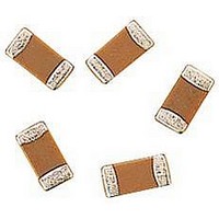
CAPACITOR CERAMIC, 0.1UF, 50V, X7R, 0805
Manufacturer
MULTICOMP
Datasheet
1.MCCA000432.pdf
(19 pages)
Specifications of U0805R104KCT
Dielectric Characteristic
X7R
Capacitance
0.1µF
Capacitance Tolerance
± 10%
Voltage Rating
50VDC
Capacitor Case Style
0805
No. Of Pins
2
Capacitor Mounting
SMD
Rohs Compliant
Yes


(1) Application of Flux:
The soldering flux(3.3) shall applied to the mounted Capacitors thinly and uniformly by forming method.
(2) Preheating:
The mounted Capacitors / Components shall be preheated sufficiently so that the “ Temperature Gradient” between the Capacitors /
Components and the melted solder shall be 150°C or below.
(3) Immersion to Soldering Bath:
The Capacitors shall be immersed into a soldering bath of 240 to 250°C for 3 to 5 seconds.
(4)Cooling:
The Capacitors shall be cooled gradually to room ambient temperature with the cooling temperature rates of 8°C/s maximum from
250°C to 170°C and 4°C/s maximum from 170°C to 130°C.
(5) Flux Cleaning:
When the Capacitors are immersed into cleaning solvent, it shall be confirmed that the surface temperature of devices do not exceed
100°C (See 3.5).
Reflow soldering.
I n reflow soldering process, the mounted Capacitors / Components are generally heated and Soldering by a thermal conduction
system such as an “Infrared radiation and hot blast soldering system” or a “Vapour Phase Soldering System (VPS)”, Large
temperature gradients such as a rapid heating and cooling in the process may cause electrical and mechanical damages if the
device. It is essential that the soldering process shall be controlled by following recommended conditions and precaution. (See
Figure7)
For Tin-Lead (Sn/Pb) Termination component:
(1) Preheating 1.
The mounted Capacitors / Components shall be preheated sufficiently, for 60 to 90 seconds so that the surface temperature of them
to be 140 to 150°C.
(2) Preheating 2.
After “Preheating 1”, the mounted Capacitors / Components shall be the elevated temperature of 150 to 200°C for 2 to 6 Seconds.
(3) Soldering:
The mounted Capacitors / Components shall be heated under the specified heating conditions (200 to 240 to 200°C for total 20 to 40
seconds, See Figure7 ) and shall be soldered at the maximum temperature of 240°C for 10 seconds of less.
(4)Cooling:
After the soldering, the mounted Capacitors / Components shall be gradually cooled to room ambient temperature for preventing
mechanical damages such as cracking of the devices.
(5) Flux Cleaning:
When the mounted Capacitors / Components are immersed into cleaning solvent, it shall be confirmed the surfaces temperatures of
them do not exceeding 100°C.
Note: If the mounted Capacitors / Components are partially heated in the soldering process, the devices may be separated form the
printed circuit board by the surface tension of partially melted solder, and stand up like a “Tomb Stone”.
Figure 7 Recommended Soldering Temperature Time Profile for Tin-Lead component (Reflow Soldering)
Nickel Barrier
Multilayer Ceramic Capacitors
Page 13
27/04/06 V1.0
Related parts for U0805R104KCT
Image
Part Number
Description
Manufacturer
Datasheet
Request
R

Part Number:
Description:
IC, LINEAR VOLTAGE REGULATOR, 15V, TO-92
Manufacturer:
MULTICOMP
Datasheet:

Part Number:
Description:
Switch Cap
Manufacturer:
MULTICOMP
Datasheet:

Part Number:
Description:
COAXIAL CABLE, 100MM, BLACK
Manufacturer:
MULTICOMP
Datasheet:

Part Number:
Description:
FUSE, PTC RESET, 16V, 3A, RADIAL
Manufacturer:
MULTICOMP
Datasheet:
Part Number:
Description:
FUSE, PTC RESET, 16V, 5A, RADIAL
Manufacturer:
MULTICOMP
Datasheet:

Part Number:
Description:
FUSE, PTC RESET, 30V, 1.85A, RADIAL
Manufacturer:
MULTICOMP
Datasheet:

Part Number:
Description:
FUSE, PTC RESET, 30V, 4A, RADIAL
Manufacturer:
MULTICOMP
Datasheet:

Part Number:
Description:
FUSE, PTC RESET, 60V, 170mA, RADIAL
Manufacturer:
MULTICOMP
Datasheet:

Part Number:
Description:
FUSE, PTC RESET, 90V, 200mA, RADIAL
Manufacturer:
MULTICOMP
Datasheet:
Part Number:
Description:
FUSE, PTC RESET, 90V, 250mA, RADIAL
Manufacturer:
MULTICOMP
Datasheet:
Part Number:
Description:
FUSE, PTC RESET, 90V, 400mA, RADIAL
Manufacturer:
MULTICOMP
Datasheet:
Part Number:
Description:
FUSE, PTC RESET, 90V, 900mA, RADIAL
Manufacturer:
MULTICOMP
Datasheet:

Part Number:
Description:
FUSE, PTC RESET, 90V, 1.6A, RADIAL
Manufacturer:
MULTICOMP
Datasheet:
Part Number:
Description:
FUSE, PTC RESET, 90V, 1.85A, RADIAL
Manufacturer:
MULTICOMP
Datasheet:

Part Number:
Description:
FUSE, PTC RESET, 16V, 750mA, SMD
Manufacturer:
MULTICOMP
Datasheet: