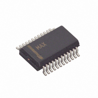
MAX5184BEEG+ Maxim Integrated Products, MAX5184BEEG+ Datasheet - Page 15

MAX5184BEEG+
Manufacturer Part Number
MAX5184BEEG+
Description
IC DAC 10BIT DUAL 40MHZ 24-QSOP
Manufacturer
Maxim Integrated Products
Datasheet
1.MAX5184ETG.pdf
(16 pages)
Specifications of MAX5184BEEG+
Settling Time
25µs
Number Of Bits
10
Data Interface
Parallel
Number Of Converters
1
Voltage Supply Source
Analog and Digital
Operating Temperature
-40°C ~ 85°C
Mounting Type
Surface Mount
Package / Case
24-QSOP
Resolution
10 bit
Interface Type
Parallel
Supply Voltage (max)
3.3 V
Supply Voltage (min)
2.7 V
Maximum Operating Temperature
+ 85 C
Mounting Style
SMD/SMT
Minimum Operating Temperature
- 40 C
Lead Free Status / RoHS Status
Lead free / RoHS Compliant
Power Dissipation (max)
-
Lead Free Status / Rohs Status
Lead free / RoHS Compliant
directly above the ground plane. Since the MAX5181/
MAX5184 have separate analog and digital ground
buses (AGND and DGND, respectively), the PC board
should also have separate analog and digital ground
sections with only one point connecting the two. Digital
signals should run above the digital ground plane, and
analog signals should run above the analog ground
plane.
Both devices have two power-supply inputs: analog
V
should be decoupled with parallel 10µF and 0.1µF
ceramic-chip capacitors. These capacitors should be
DD
(AV
TOP VIEW
Pin Configurations (continued)
DACEN
DD
AGND
10-Bit, 40MHz, Current/Voltage-Output DACs
AV
CLK
PD
CS
DD
) and digital V
+
1
2
3
4
5
6
______________________________________________________________________________________
MAX5184
DD
TQFN-EP
(DV
DD
). Each AV
EP
18
17
16
15
14
13
DV
D9
D8
D7
D6
D5
DD
DD
input
as close to the pin as possible, and their opposite ends
should be as close as possible to the ground plane.
The DV
0.1µF capacitors adjacent to their respective pins. Try
to minimize analog load capacitance for proper opera-
tion. For best performance, bypass with low-ESR 0.1µF
capacitors to AV
The power-supply voltages should also be decoupled
with large tantalum or electrolytic capacitors at the
point they enter the PC board. Ferrite beads with addi-
tional decoupling capacitors forming a pi network can
also improve performance.
For the latest package outline information and land patterns, go
to www.maxim-ic.com/packages. Note that a “+”, “#”, or “-” in
the package code indicates RoHS status only. Package draw-
ings may show a different suffix character, but the drawing per-
tains to the package regardless of RoHS status.
SUBSTRATE CONNECTED TO AGND
PACKAGE
24 QSOP
24 TQFN
TYPE
DD
pins should also have separate 10µF and
PACKAGE
DD
T2444+4
CODE
E24+1
.
Package Information
Chip Information
OUTLINE
21-0055
21-0139
NO.
PATTERN NO
90-0172
90-0222
LAND
15


