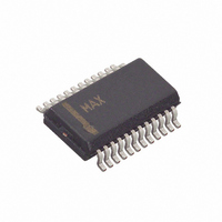
MAX5184BEEG+ Maxim Integrated Products, MAX5184BEEG+ Datasheet - Page 14

MAX5184BEEG+
Manufacturer Part Number
MAX5184BEEG+
Description
IC DAC 10BIT DUAL 40MHZ 24-QSOP
Manufacturer
Maxim Integrated Products
Datasheet
1.MAX5184ETG.pdf
(16 pages)
Specifications of MAX5184BEEG+
Settling Time
25µs
Number Of Bits
10
Data Interface
Parallel
Number Of Converters
1
Voltage Supply Source
Analog and Digital
Operating Temperature
-40°C ~ 85°C
Mounting Type
Surface Mount
Package / Case
24-QSOP
Resolution
10 bit
Interface Type
Parallel
Supply Voltage (max)
3.3 V
Supply Voltage (min)
2.7 V
Maximum Operating Temperature
+ 85 C
Mounting Style
SMD/SMT
Minimum Operating Temperature
- 40 C
Lead Free Status / RoHS Status
Lead free / RoHS Compliant
Power Dissipation (max)
-
Lead Free Status / Rohs Status
Lead free / RoHS Compliant
10-Bit, 40MHz, Current/Voltage-Output DACs
ture stability, wide-band tuning, and past phase-contin-
uos frequency switching, the user may approach a
direct digital synthesis (DDS) AWG (Figure 8b). This
DDS loop supports standard waveforms that are repeti-
tive, such as sine, square, TTL, and triangular wave-
forms. DDS allows for precise control of the
data-stream input to the DAC. Data for one complete
output waveform cycle is sequentially stored in a RAM.
As the RAM addresses are changing, the DAC con-
verts the incoming data bits into a corresponding volt-
age waveform. The resulting output signal frequency is
proportional to the frequency rate at which the RAM
addresses are changed.
Figure 8a. Traditional Arbitrary Waveform Generation
Figure 8b. Direct Digital Synthesis AWG
14
*MAX5181 ONLY
______________________________________________________________________________________
INCREMENT
REGISTER
PHASE
GENERATOR
*MAX5181 ONLY
PIR
CLOCK
A
D
D
R
E
COUNTER
CLOCK
GENERATOR
FEEDBACK LOOP
ACCUMULATOR
FOR DATA BITS
ACCUMULATOR
PHASE
ADR
ADR
WAVEFORM
MEMORY
(RAM)
WAVEFORM
MEMORY
(RAM)
DATA
10
9.6kΩ*
DATA
10
Grounding and power-supply decoupling strongly influ-
ence the MAX5181/MAX5184’s performance. Unwanted
digital crosstalk may couple through the input, refer-
ence, power-supply, and ground connections, which
may affect dynamic specifications like SNR or SFDR. In
addition, electromagnetic interference (EMI) can either
couple into or be generated by the MAX5181/
MAX5184. Therefore, grounding and power-supply
decoupling guidelines for high-speed, high-frequency
applications should be closely followed.
First, a multilayer PC board with separate ground and
power-supply planes is recommended. High-speed
signals should be run on controlled impedance lines
9.6kΩ*
AV
Grounding and Power-Supply Decoupling
DD
MAX5181
MAX5184
AV
DD
DV
MAX5181
MAX5184
DD
DV
DD
400Ω*
400Ω*
RECONSTRUCTION
RECONSTRUCTION
LOWPASS
VARIABLE
FILTER
LOWPASS
VARIABLE
fc
FILTER
fc
(ANALOG OUTPUT)
(ANALOG OUTPUT)
WAVEFORM
FILTERED
WAVEFORM
FILTERED


