148384-5 TE Connectivity, 148384-5 Datasheet - Page 17
148384-5
Manufacturer Part Number
148384-5
Description
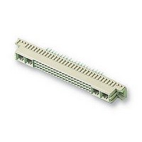
SOCKET, DIN41612, STRAIGHT, M, 24+8WAY
Manufacturer
TE Connectivity
Datasheet
1.148384-5.pdf
(18 pages)
Specifications of 148384-5
Connector Type
Pitch Spacing
No. Of Contacts
32
Gender
Receptacle
No. Of Rows
3
Rows Loaded
A + B + C
Contact Termination
Through Hole
Contact Material
Phosphor Bronze
Contact
RoHS Compliant
Pitch Spacing
2.54mm
Contact Plating
Gold
Rohs Compliant
Yes
Product Series
Type M
Mount Angle
Vertical
Post Type
Compliant Post
Din Level
II
Loaded With Single Contacts Only
Yes
Color
Gray
Toolless (flat Rock)
Yes
Termination Post Length (mm [in])
6.00 [0.236]
Solder Tail Contact Plating
Tin-Lead over Nickel
Number Of Signal Contacts
24
Contact Type
Socket
Number Of Power Or Coaxial Contacts
8
Preloaded
Yes
Contact Configuration
Coaxial, Power
Contact Base Material
Phosphor Bronze
Contact Plating, Mating Area, Material
Gold Flash over Palladium Nickel
Connector Style
Receptacle
Housing Material
Thermoplastic - GF
Ul Flammability Rating
UL 94V-0
Rohs/elv Compliance
RoHS compliant, ELV compliant
Lead Free Solder Processes
Not relevant for lead free process
Rohs/elv Compliance History
Always was RoHS compliant
Pcb Thickness, Recommended (mm [in])
1.57 [0.062]
Application
Board-to-Board Power


5.5. Connector Replacement Tooling
When entire Type C receptacle connectors and Type R pin connectors must be replaced, Eurocard Connector
Removal Tool Kit 534611--1 should be used. Refer to Figure 16 and proceed as follows:
5.6. Contact Extraction Tooling
Extraction tooling is available for withdrawal of individual power contacts and coaxial contacts from Type M
connectors. The tip of the tool is inserted into the contact cavity from the mating side of the housing. The
contact is forced out of the rear of the housing by pushing the tool handle. See Figure 16.
Rev G
CAUTION
Support Block
!
1. Place support block with slot up on the arbor frame support base.
2. Place housing down on support block with pins extending up through pc board.
3. Slide guide block over wire--wrap tails. Be sure the “T” stamp on end of guide block is away from pc
board.
4. Start push--out assembly into guide block, using care not to damage pins.
5. Lower the arbor ram onto the center of push--out assembly and apply force until it is seated on guide
block.
6. Raise the arbor ram and remove push--out assembly and guide block. When the board, the
connector, and the support block are removed, the connector will fall away with pins removed from the
pc board and housing.
Guide Block
Push- - Out
Assembly
“T” Stamp
Slot
DO NOT use this tool in a power assist unit. This procedure should be done with a manually operated unit only.
Ram
Figure 16
Pins
PC Board
Connector
Extraction Tool
106242- - 1
114- 9014
17 of 18
Related parts for 148384-5
Image
Part Number
Description
Manufacturer
Datasheet
Request
R

Part Number:
Description:
Printers THERMAL PRINTER HS-SLEEVE MARKER
Manufacturer:
TE Connectivity


Part Number:
Description:
High Speed / Modular Connectors 30P HEADER ASSY
Manufacturer:
TE Connectivity
Datasheet:

Part Number:
Description:
High Speed / Modular Connectors REC 6X005P R/A LT B-PLANE HS3
Manufacturer:
TE Connectivity
Datasheet:

Part Number:
Description:
High Speed / Modular Connectors 2MM HM RCPT 50P R/A AU
Manufacturer:
TE Connectivity
Datasheet:

Part Number:
Description:
High Speed / Modular Connectors 2MM HM RCPT 50P R/A AU
Manufacturer:
TE Connectivity
Datasheet:


Part Number:
Description:
Manufacturer:
TE Connectivity
Datasheet:


Part Number:
Description:
Manufacturer:
TE Connectivity
Datasheet:

Part Number:
Description:
Manufacturer:
TE Connectivity
Datasheet:

Part Number:
Description:
Manufacturer:
TE Connectivity
Datasheet: