148384-5 TE Connectivity, 148384-5 Datasheet - Page 13
148384-5
Manufacturer Part Number
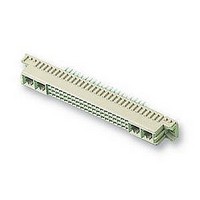
148384-5
Description
SOCKET, DIN41612, STRAIGHT, M, 24+8WAY
Manufacturer
TE Connectivity
Datasheet
1.148384-5.pdf
(18 pages)
Specifications of 148384-5
Connector Type
Pitch Spacing
No. Of Contacts
32
Gender
Receptacle
No. Of Rows
3
Rows Loaded
A + B + C
Contact Termination
Through Hole
Contact Material
Phosphor Bronze
Contact
RoHS Compliant
Pitch Spacing
2.54mm
Contact Plating
Gold
Rohs Compliant
Yes
Product Series
Type M
Mount Angle
Vertical
Post Type
Compliant Post
Din Level
II
Loaded With Single Contacts Only
Yes
Color
Gray
Toolless (flat Rock)
Yes
Termination Post Length (mm [in])
6.00 [0.236]
Solder Tail Contact Plating
Tin-Lead over Nickel
Number Of Signal Contacts
24
Contact Type
Socket
Number Of Power Or Coaxial Contacts
8
Preloaded
Yes
Contact Configuration
Coaxial, Power
Contact Base Material
Phosphor Bronze
Contact Plating, Mating Area, Material
Gold Flash over Palladium Nickel
Connector Style
Receptacle
Housing Material
Thermoplastic - GF
Ul Flammability Rating
UL 94V-0
Rohs/elv Compliance
RoHS compliant, ELV compliant
Lead Free Solder Processes
Not relevant for lead free process
Rohs/elv Compliance History
Always was RoHS compliant
Pcb Thickness, Recommended (mm [in])
1.57 [0.062]
Application
Board-to-Board Power


3.8. Soldering
Connectors with solder contacts can be mounted on and secured to a pc board by hand soldering or wave
soldering techniques.
ALPHA, BIOACT, CARBITOL, KESTER, and LONCOTERGE are trademarks of their respective owners.
Rev G
CAUTION
C. Mating Conditions
To ensure reliable connections and prevent unnecessary damage to connectors, refer to the
recommended vertical alignment and offset tolerances shown in Figure 11.
A. Flux Selection
Solder tines and pc board attaching hardware must be fluxed prior to soldering. Selection of the flux will
depend on the type of pc board used and other components that may be mounted on the board. Also, the
choice will have to be compatible with the wave solder line, manufacturing, and safety requirements.
B. Cleaning
Fluxes, residues, and activators must be removed. Cleaning procedures depend on the type of flux used
on the solder line. The following cleaning compounds and chemicals may be used to clean the connectors
without adverse affect on the housings and contacts. See Figure 12.
!
ALPHA 2110
BIOACT EC--7
Butyl CARBITOL
Isopropyl Alcohol
KESTER 5778
KESTER 5779
LONCOTERGE 520
LONCOTERGE 530
Terpene Solvent
DISCONNECT electrical current before mating or unmating connectors.
1.02 [.040]
NAME
Vertical Alignment
CLEANER
1.02 [.040]
Aqueous
Aqueous
Aqueous
Aqueous
Aqueous
Solvent
Solvent
Solvent
Solvent
TYPE
Figure 11
Figure 12
(Minutes)
TIME
TIME
1
5
1
5
5
5
5
5
5
+4_
Offset Tolerances
TEMPERATURE
TEMPERATURE
132_C [270_F]
100_C [212_F]
100_C [212_F]
100_C [212_F]
100_C [212_F]
100_C [212_F]
100_C [212_F]
100_C [212_F]
Ambient Room
(Maximum)
+2_
114- 9014
13 of 18
Related parts for 148384-5
Image
Part Number
Description
Manufacturer
Datasheet
Request
R

Part Number:
Description:
Printers THERMAL PRINTER HS-SLEEVE MARKER
Manufacturer:
TE Connectivity


Part Number:
Description:
High Speed / Modular Connectors 30P HEADER ASSY
Manufacturer:
TE Connectivity
Datasheet:

Part Number:
Description:
High Speed / Modular Connectors REC 6X005P R/A LT B-PLANE HS3
Manufacturer:
TE Connectivity
Datasheet:

Part Number:
Description:
High Speed / Modular Connectors 2MM HM RCPT 50P R/A AU
Manufacturer:
TE Connectivity
Datasheet:

Part Number:
Description:
High Speed / Modular Connectors 2MM HM RCPT 50P R/A AU
Manufacturer:
TE Connectivity
Datasheet:


Part Number:
Description:
Manufacturer:
TE Connectivity
Datasheet:


Part Number:
Description:
Manufacturer:
TE Connectivity
Datasheet:

Part Number:
Description:
Manufacturer:
TE Connectivity
Datasheet:

Part Number:
Description:
Manufacturer:
TE Connectivity
Datasheet: