2007637-5 TE Connectivity, 2007637-5 Datasheet - Page 7
2007637-5
Manufacturer Part Number
2007637-5
Description
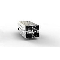
CAGE, STACKED, 2X2, SFP+, LIGHT
Manufacturer
TE Connectivity
Datasheet
1.2007637-5.pdf
(10 pages)
Specifications of 2007637-5
Connector Type
Cage
Contact Termination
Press Fit
Connector Mounting
PCB
Contact Plating
Gold
Contact Material
Copper Alloy
Connector Mounting Orientation
PCB
Rohs Compliant
Yes
No. Of Contacts
4
Svhc
No SVHC (15-Dec-2010)
Product Type
Cage
Termination Type
Press-Fit
Configuration
2 x 2
Pcb Mount
Single Sided
Termination Post Length (mm [in])
3.00 [0.118]
Contact Plating, Mating Area, Material
Gold or Gold Flash over Palladium Nickel
Contact Base Material
Copper Alloy
Cage Type
Stacked
Housing Color
Black
Ul Flammability Rating
UL 94V-0
Housing Material
Liquid Crystal Polymer (LCP)
Cage Material
Nickel Silver
Emi Containment
External Springs
Lightpipe
With
Rohs/elv Compliance
RoHS compliant, ELV compliant
Lead Free Solder Processes
Not relevant for lead free process
Rohs/elv Compliance History
Always was RoHS compliant
Application
SFP+
Lightpipe Configuration
Four Per Column
Packaging Method
Tray
Available stocks
Company
Part Number
Manufacturer
Quantity
Price
Company:

Part Number:
2007637-5
Manufacturer:
TYCO
Quantity:
36 560


3.10. Placement
The following requirements also apply to connectors and cage assemblies used for rework purposes.
Rev B
CAUTION
CAUTION
NOTE
A. Registration
The compliant pin contacts and mounting posts must be aligned with matching holes in the pc board, then
inserted into the pc board simultaneously to prevent twisting or bending of the compliant pin contacts.
B. Seating
Using proper seating force and seating height is essential to interconnection performance. The force used
to seat the connector and cage assembly must be applied evenly to prevent deformation or other damage
to the compliant pin contacts. The force required to seat the connector and cage assembly onto the pc
board can be calculated by:
The shut height of the application tool must be specifically set for proper seating of the connector and
cage assembly. The shut height can be calculated by:
The seating height, measured from the top of the cage assembly (not including the panel grounding
feature) to the top of the pc board, is given in Figure 5.
The connector and cage assembly must be seated on the pc board not exceeding the dimensions shown
in Figure 5.
!
!
i
Amount of Compliant Pin Contacts ¢ 44.5 N [10 lbs] (Force per Compliant Pin Contact) = Seating Force
Seating Height (Connector and Cage Assembly Seated) + Height of Seating Tool + Combined
Thicknesses of PC Board and PC Board Support Fixture = Shut Height (Ram Down)
Compliant Pin Contacts
To avoid damage to elastomeric gasket, panel ground springs, and compliant tails, handle only by cage sides.
Over- - driving of the connector and cage assembly will deform parts critical to the quality of the connection. Maximum
force occurs prior to the connector and cage assembly bottoming on the pc board.
The shut height may need to be adjusted to obtain the 0.10 mm maximum gap between the standoffs of the cage
assembly and the pc board.
Cage Assembly
Figure 5
Mounting Posts
(Top of Cage Assembly, Not Including
Panel Ground Springs, to PC Board)
25.5 Seating Height
0.10 (Max) Gap
Cage Assembly Standoffs
to PC Board
Connector
114- 13219
7 of 10
Related parts for 2007637-5
Image
Part Number
Description
Manufacturer
Datasheet
Request
R


Part Number:
Description:
I/O CONNECTOR, RECEPTACLE, 200POS, SMD
Manufacturer:
Molex Inc
Datasheet:

Part Number:
Description:
I/O Connectors Stacked SFP 2x5 Asse 2x5 Assembly Medium
Manufacturer:
Molex Inc

Part Number:
Description:
I/O Connectors Stacked SFP 2x5 Med P 2x5 Med Assy W/ LP
Manufacturer:
Molex Inc
Part Number:
Description:
I/O Connectors Stacked SFP 2x5 Asse ssembly w Lightpipe
Manufacturer:
Molex Inc

Part Number:
Description:
High Speed / Modular Connectors 30P HEADER ASSY
Manufacturer:
TE Connectivity
Datasheet:

Part Number:
Description:
High Speed / Modular Connectors REC 6X005P R/A LT B-PLANE HS3
Manufacturer:
TE Connectivity
Datasheet:

Part Number:
Description:
High Speed / Modular Connectors 2MM HM RCPT 50P R/A AU
Manufacturer:
TE Connectivity
Datasheet:

Part Number:
Description:
High Speed / Modular Connectors 2MM HM RCPT 50P R/A AU
Manufacturer:
TE Connectivity
Datasheet:


Part Number:
Description:
Manufacturer:
TE Connectivity
Datasheet:


Part Number:
Description:
Manufacturer:
TE Connectivity
Datasheet:

Part Number:
Description:
Manufacturer:
TE Connectivity
Datasheet:

Part Number:
Description:
Manufacturer:
TE Connectivity
Datasheet: