2007637-5 TE Connectivity, 2007637-5 Datasheet
2007637-5
Specifications of 2007637-5
Available stocks


Related parts for 2007637-5


2007637-5 Summary of contents
Page 1
... When corresponding with TE Personnel, use the terminology provided in this specification to facilitate your inquiries for information. Basic terms and features of this product are provided in Figure 1. E2011 Tyco Electronics Corporation Connectivity Ltd. Company All Rights Reserved TE logo is a trademark. ...
Page 2
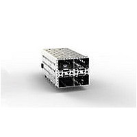
Connector Housing Card Entry Slot Alignment Compliant Post Tails 2. REFERENCE MATERIAL 2.1. Revision Summary Updated document to corporate requirements. S 2.2. Customer Assistance Reference Product Base Part Number 2007399 and Product Code K638 are representative of Stacked SFP+ Connector ...
Page 3
REQUIREMENTS 3.1. Safety Do not stack component packages so high that the shipping containers buckle or deform. 3.2. Limitations The connectors are designed to operate in a temperature range of --55_ to 105_C [--67_ to 221_F]. The bezel requirements ...
Page 4
Recommended Hole Dimensions For Connector 0.54- - 0.58 Drilled Hole Diameter 0.46 Ref Finished Hole Diameter After Plating THICKNESS 0.004--0.010 0.0005--0.002 0.0002--0.0005 0.0001--0.0005 Au, 0.004--0.0076 Ni 0.0001--0.0005 Keep- - Out Zone (Detail G) 1.90 7.11 7.85 Light Pipe Pad Layout ...
Page 5
SEE DETAIL F 12X 51.625 42 1.05 (Ref) BSC 4X 14.25 0 40X 0.46 (Ref) 0.1 D 6.52 5.14 ...
Page 6
Transceiver Modules CAUTION The mating transceiver module packing size cannot exceed the width of each cage port opening. This includes the part of the transceiver that is extending outside the cage. Since the port- - to- - port spacing ...
Page 7
Placement The following requirements also apply to connectors and cage assemblies used for rework purposes. CAUTION To avoid damage to elastomeric gasket, panel ground springs, and compliant tails, handle only by cage sides Registration The compliant pin ...
Page 8
Checking Assembly After assembly, the cage assembly panel grounding feature must be compressed by the bezel. A slight bow in the cage assembly is permitted. The bezel and pc board must positioned according to the dimensions shown in Figure ...
Page 9
Seating Tool Kits The seating tool kits (each consists of a seating tool and wall support) are used to seat the connector and cage assembly onto the pc board. The seating tool and wall support are also available separately. ...
Page 10
VISUAL AID Figure 8 shows a typical application of stacked a SFP+ Connector and Cage Assembly. This illustration should be used by production personnel to ensure a correctly applied product. Applications which DO NOT appear correct should be inspected ...