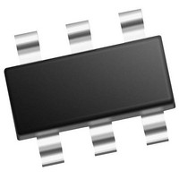
PIC10F322T-I/OT Microchip Technology, PIC10F322T-I/OT Datasheet - Page 39

PIC10F322T-I/OT
Manufacturer Part Number
PIC10F322T-I/OT
Description
896 B Flash, 64 B RAM, 4 I/O, 8bit ADC, PWM, CLC, DDS, CWG, TEMP Indicator, 2.3V
Manufacturer
Microchip Technology
Datasheet
1.PIC10F320-IOT.pdf
(210 pages)
Specifications of PIC10F322T-I/OT
Core
RISC
Processor Series
PIC10F
Data Bus Width
8 bit
Maximum Clock Frequency
31 KHz
Program Memory Size
512 B
Data Ram Size
64 B
Number Of Programmable I/os
4
Number Of Timers
2
Operating Temperature Range
- 40 C to + 85 C
Package / Case
SOT-23-6
Mounting Style
SMD/SMT
Maximum Operating Temperature
+ 85 C
Program Memory Type
Flash
Lead Free Status / Rohs Status
Details
Available stocks
Company
Part Number
Manufacturer
Quantity
Price
Company:
Part Number:
PIC10F322T-I/OT
Manufacturer:
VISHAY
Quantity:
11 490
Part Number:
PIC10F322T-I/OT
Manufacturer:
MICROCHIP/微芯
Quantity:
20 000
- Current page: 39 of 210
- Download datasheet (2Mb)
5.10
The Power Control (PCON) register contains flag bits
to differentiate between a:
• Power-on Reset (POR)
• Brown-out Reset (BOR)
The PCON register bits are shown in
REGISTER 5-2:
TABLE 5-5:
TABLE 5-6:
2011 Microchip Technology Inc.
BORCON
PCON
STATUS
WDTCON
Legend: — = unimplemented location, read as ‘0’. Shaded cells are not used by Resets.
CONFIG
Legend: — = unimplemented location, read as ‘0’. Shaded cells are not used by clock sources.
bit 7
Legend:
HC = Bit is cleared by hardware
R = Readable bit
u = Bit is unchanged
‘1’ = Bit is set
bit 7-2
bit 1
bit 0
Name
Name
U-0
—
Power Control (PCON) Register
13:8
Bits
SBOREN
7:0
Bit 7
IRP
Unimplemented: Read as ‘0’
POR: Power-on Reset Status bit
1 = No Power-on Reset occurred
0 = A Power-on Reset occurred (must be set in software after a Power-on Reset occurs)
BOR: Brown-out Reset Status bit
1 = No Brown-out Reset occurred
0 = A Brown-out Reset occurred (must be set in software after a Power-on Reset or Brown-out Reset
—
—
SUMMARY OF REGISTERS ASSOCIATED WITH RESETS
SUMMARY OF CONFIGURATION WORD WITH RESETS
Bit -/7
CP
occurs)
—
U-0
—
PCON: POWER CONTROL REGISTER
BORFS
Bit 6
RP1
—
—
MCLRE
Bit -/6
W = Writable bit
x = Bit is unknown
‘0’ = Bit is cleared
—
U-0
—
Register
Bit 5
RP0
—
—
Bit 13/5
PWRTE
—
5-2.
U-0
Bit 4
Preliminary
—
TO
Bit 12/4
—
—
WDTE<1:0>
WRT<1:0>
WDTPS<4:0>
U = Unimplemented bit, read as ‘0’
-n/n = Value at POR and BOR/Value at all other Resets
q = Value depends on condition
Bit 3
PD
—
—
Bit 11/3
U-0
—
PIC10(L)F320/322
Bit 2
Bit 10/2
—
—
Z
BORV
BOREN<1:0>
U-0
—
Bit 1
POR
LPBOR
DC
Bit 9/1
—
R/W/HC-q/u
POR
BORRDY
SWDTEN
Bit 0
BOR
Bit 8/0
FOSC
C
LVP
DS41585A-page 39
R/W/HC-q/u
Register
on Page
Register
on Page
BOR
35
39
15
55
22
bit 0
Related parts for PIC10F322T-I/OT
Image
Part Number
Description
Manufacturer
Datasheet
Request
R

Part Number:
Description:
896 B Flash, 64 B RAM, 4 I/O, 8bit ADC, PWM, CLC, DDS, CWG, TEMP Indicator, 2.3V
Manufacturer:
Microchip Technology

Part Number:
Description:
896 B Flash, 64 B RAM, 4 I/O, 8bit ADC, PWM, CLC, DDS, CWG, TEMP Indicator, 2.3V
Manufacturer:
Microchip Technology

Part Number:
Description:
896 B Flash, 64 B RAM, 4 I/O, 8bit ADC, PWM, CLC, DDS, CWG, TEMP Indicator, 2.3V
Manufacturer:
Microchip Technology

Part Number:
Description:
896 B Flash, 64 B RAM, 4 I/O, 8bit ADC, PWM, CLC, DDS, CWG, TEMP Indicator, 2.3V
Manufacturer:
Microchip Technology

Part Number:
Description:
896 B Flash, 64 B RAM, 4 I/O, 8bit ADC, PWM, CLC, DDS, CWG, TEMP Indicator, 2.3V
Manufacturer:
Microchip Technology

Part Number:
Description:
896 B Flash, 64 B RAM, 4 I/O, 8bit ADC, PWM, CLC, DDS, CWG, TEMP Indicator, 2.3V
Manufacturer:
Microchip Technology

Part Number:
Description:
384B Flash, 16B RAM, 4 I/O, 8bit ADC 6 SOT-23 BAG
Manufacturer:
Microchip Technology
Datasheet:

Part Number:
Description:
768B Flash, 23B RAM, 4 I/O, 8bit ADC 6 SOT-23 BAG
Manufacturer:
Microchip Technology
Datasheet:

Part Number:
Description:
384B Flash, 16B RAM, 4 I/O, 8bit ADC 6 SOT-23 BAG
Manufacturer:
Microchip Technology
Datasheet:

Part Number:
Description:
768B Flash, 23B RAM, 4 I/O, 8bit ADC 6 SOT-23 BAG
Manufacturer:
Microchip Technology
Datasheet:

Part Number:
Description:
PIC10F PROGRAMMER ADAPTER (SOT-23), PICKIT
Manufacturer:
Microchip Technology Inc.

Part Number:
Description:
Manufacturer:
Microchip Technology Inc.
Datasheet:

Part Number:
Description:
Manufacturer:
Microchip Technology Inc.
Datasheet:


