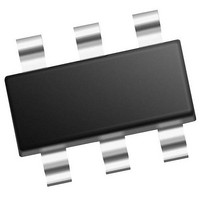
PIC10F322T-I/OT Microchip Technology, PIC10F322T-I/OT Datasheet - Page 28

PIC10F322T-I/OT
Manufacturer Part Number
PIC10F322T-I/OT
Description
896 B Flash, 64 B RAM, 4 I/O, 8bit ADC, PWM, CLC, DDS, CWG, TEMP Indicator, 2.3V
Manufacturer
Microchip Technology
Datasheet
1.PIC10F320-IOT.pdf
(210 pages)
Specifications of PIC10F322T-I/OT
Core
RISC
Processor Series
PIC10F
Data Bus Width
8 bit
Maximum Clock Frequency
31 KHz
Program Memory Size
512 B
Data Ram Size
64 B
Number Of Programmable I/os
4
Number Of Timers
2
Operating Temperature Range
- 40 C to + 85 C
Package / Case
SOT-23-6
Mounting Style
SMD/SMT
Maximum Operating Temperature
+ 85 C
Program Memory Type
Flash
Lead Free Status / Rohs Status
Details
Available stocks
Company
Part Number
Manufacturer
Quantity
Price
Company:
Part Number:
PIC10F322T-I/OT
Manufacturer:
VISHAY
Quantity:
11 490
Part Number:
PIC10F322T-I/OT
Manufacturer:
MICROCHIP/微芯
Quantity:
20 000
PIC10(L)F320/322
4.2
Clock source modes can be classified as external or
internal.
• Internal clock source (INTOSC) is contained
• The External Clock mode (EC) relies on an
The system clock can be selected between external or
internal clock sources via the FOSC bit of the
Configuration Word.
4.3
The internal clock sources are contained within the
oscillator module. The internal oscillator block has two
internal oscillators that are used to generate all internal
system clock sources: the 16 MHz High-Frequency
Internal Oscillator (HFINTOSC) and the 31 kHz
(LFINTOSC).
The HFINTOSC consists of a primary and secondary
clock. The secondary clock starts first with rapid start-
up time, but low accuracy. The secondary clock ready
signal is indicated with the HFIOFR bit of the OSCCON
register. The primary clock follows with slower start-up
time and higher accuracy. The primary clock is stable
when the HFIOFS bit of the OSCCON register bit goes
high.
4.3.1
When the FOSC bit of the Configuration Word is
cleared, the INTOSC mode is selected. When INTOSC
is selected, CLKIN pin is available for general purpose
I/O. See
more information.
DS41585A-page 28
within the oscillator module, which has eight
selectable output frequencies, with a maximum
internal frequency of 16 MHz.
external signal for the clock source.
Clock Source Modes
Internal Clock Modes
Section 3.0 “Device Configuration”
INTOSC MODE
Preliminary
for
4.3.2
The output of the 16 MHz HFINTOSC is connected to
a divider and multiplexer (see
Oscillator Frequency Select bits (IRCF) of the
OSCCON register select the frequency output of the
internal oscillator:
• HFINTOSC
• LFINTOSC
There is no delay when switching between HFINTOSC
frequencies with the IRCF bits. This is because the
switch involves only a change to the frequency output
divider.
Start-up
Section 24.0 “Electrical
- 16 MHz
- 8 MHz (default after Reset)
- 4 MHz
- 2 MHz
- 1 MHz
- 500 kHz
- 250 kHz
- 31 kHz
Note:
delay
FREQUENCY SELECT BITS (IRCF)
Following any Reset, the IRCF<2:0> bits
of the OSCCON register are set to ‘110’
and the frequency selection is set to
8 MHz. The user can modify the IRCF bits
to select a different frequency.
specifications
2011 Microchip Technology Inc.
Specifications”.
Figure
are
4-1). The Internal
located
in


