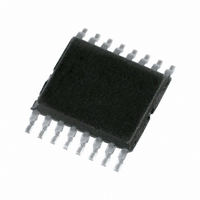
PCA9691TS/1,118 NXP Semiconductors, PCA9691TS/1,118 Datasheet - Page 21

PCA9691TS/1,118
Manufacturer Part Number
PCA9691TS/1,118
Description
IC ADC/DAC 8-BIT I2C 16-TSSOP
Manufacturer
NXP Semiconductors
Type
ADC, DACr
Datasheet
1.PCA9691BS1118.pdf
(31 pages)
Specifications of PCA9691TS/1,118
Package / Case
16-TSSOP
Resolution (bits)
8 b
Data Interface
I²C, Serial
Voltage Supply Source
Single Supply
Voltage - Supply
2.5 V ~ 5.5 V
Operating Temperature
-40°C ~ 85°C
Mounting Type
Surface Mount
Mounting Style
SMD/SMT
Lead Free Status / RoHS Status
Lead free / RoHS Compliant
Sampling Rate (per Second)
-
Lead Free Status / Rohs Status
Lead free / RoHS Compliant
Other names
935283384118
PCA9691TS/1-T
PCA9691TS/1-T
PCA9691TS/1-T
PCA9691TS/1-T
Available stocks
Company
Part Number
Manufacturer
Quantity
Price
Company:
Part Number:
PCA9691TS/1,118
Manufacturer:
NXP
Quantity:
560
NXP Semiconductors
Table 9.
V
specified.
PCA9691_2
Product data sheet
Symbol
Analog inputs
V
I
C
C
V
V
Accuracy
E
E
E
CMRR
α
t
f
LI
c(ADC)
c(ADC)
DD
sup(n)
AIN
i(se)
i(dif)
G
O
L
i(a)
i(dif)
= 5.0 V; V
A/D characteristics
Parameter
voltage on pin AIN
input leakage current
analog input capacitance
differential input capacitance
single-ended input voltage
differential input voltage
gain error
offset error
linearity error
common-mode rejection ratio
noise suppression
ADC conversion time
ADC conversion frequency
SS
= 0 V; V
Table 8.
V
C
[1]
[2]
VREF
Symbol Parameter
Analog output
V
I
Accuracy
E
E
E
t
f
α
LO
s(DAC)
c(DAC)
DD
L
sup(n)
AOUT
G
O
L
= 50 pF; unless otherwise specified.
= 5.0 V; V
The linearity error is assured if the internal frequency is changed by setting bit 7 and bit 3 of the control byte
to logic 1 (see
The time from the start of AOUT to a change of
= 5.0 V; V
voltage on pin AOUT
output leakage current
gain error
offset error
linearity error
DAC settling time
DAC conversion frequency
noise suppression
D/A characteristics
SS
AGND
= 0 V; V
Figure
Conditions
pins AIN0 to AIN3
measuring range
measuring range:
V
f
f
f
f
f = 100 Hz;
V
f
SCL
SCL
SCL
SCL
SCL
FSR
n(VDD)(p-p)
= 0 V; T
≤ 400 kHz
> 400 kHz
≤ 400 kHz
> 400 kHz
= 1 MHz
6).
Rev. 02 — 27 January 2010
= V
VREF
VREF
amb
= 100 mV
= 5.0 V; V
=
− V
−
40
AGND
°
Conditions
no resistive load
R
pin AOUT disabled
no resistive load
f
f
f = 100 Hz;
V
C to +85
SCL
SCL
AGND
n(VDD)(p-p)
L
= 10 kΩ
≤ 400 kHz
> 400 kHz
= 0 V; T
[1]
[1]
1
⁄
2
°
LSB full scale (see
C; R
Min
V
−100
-
-
V
−0.5V
-
-
-
-
-
-
-
-
-
= 100 mV
SS
AGND
amb
L
FSR
= 10 k
=
−
40
Ω
Typ
-
-
10
10
-
-
-
-
-
-
-
40
40
-
-
[1]
[1]
[2]
; C
°
C to +85
Min
V
V
−100
-
-
-
-
-
-
-
8-bit A/D and D/A converter
Section
L
SS
SS
= 50 pF; unless otherwise
°
7.3).
Typ
-
-
-
-
-
-
-
-
-
40
Max
V
+100
-
-
V
+0.5V
1
3
±20
±1.0
±2.0
-
-
8.5
111
C; R
DD
VREF
PCA9691
© NXP B.V. 2010. All rights reserved.
L
FSR
Max
V
0.9V
+100
1
±20
±1.0
±1.5
2.4
44
-
= 10 k
DD
DD
Unit
V
nA
pF
pF
V
V
%
%
mV
LSB
LSB
dB
dB
μs
kHz
Ω
;
21 of 31
Unit
V
V
nA
%
mV
LSB
LSB
μs
kHz
dB


