AD872AJE Analog Devices Inc, AD872AJE Datasheet - Page 6
AD872AJE
Manufacturer Part Number
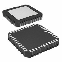
AD872AJE
Description
IC ADC 12BIT 10MSPS 44-CLCC
Manufacturer
Analog Devices Inc
Datasheet
1.AD872AJD.pdf
(20 pages)
Specifications of AD872AJE
Rohs Status
RoHS non-compliant
Number Of Bits
12
Sampling Rate (per Second)
10M
Data Interface
Parallel
Number Of Converters
7
Power Dissipation (max)
1.3W
Voltage Supply Source
Analog and Digital, Dual ±
Operating Temperature
0°C ~ 70°C
Mounting Type
Surface Mount
Package / Case
44-CLCC
Available stocks
Company
Part Number
Manufacturer
Quantity
Price


AD872A
DEFINITIONS OF SPECIFICATIONS
LINEARITY ERROR (INL)
Linearity error refers to the deviation of each individual code
from a line drawn from “negative full scale” through “positive
full scale.” The point used as “negative full scale” occurs
1/2 LSB before the first code transition. “Positive full scale” is
defined as a level 1 1/2 LSB beyond the last code transition.
The deviation is measured from the middle of each particular
code to the true straight line.
DIFFERENTIAL LINEARITY ERROR (DNL, NO MISSING
CODES)
An ideal ADC exhibits code transitions that are exactly 1 LSB
apart. DNL is the deviation from this ideal value. Guaranteed
no missing codes to 12-bit resolution indicates that all 4096
codes must be present over all operating ranges.
ZERO ERROR
The major carry transition should occur for an analog value
1/2 LSB below analog common. Zero error is defined as the
deviation of the actual transition from that point. The zero error
and temperature drift specify the initial deviation and maximum
change in the zero error over temperature.
GAIN ERROR
The first code transition should occur for an analog value
1/2 LSB above nominal negative full scale. The last transition
should occur for an analog value 1 1/2 LSB below the nominal
positive full scale. Gain error is the deviation of the actual differ-
ence between first and last code transitions and the ideal differ-
ence between first and last code transitions.
TEMPERATURE DRIFT
The temperature drift for zero error and gain error specifies the
maximum change from the initial (+25 C) value to the value at
T
POWER SUPPLY REJECTION
The specifications show the maximum change in the converter’s
full scale as the supplies are varied from nominal to min/max
values.
APERTURE JITTER
Aperture jitter is the variation in aperture delay for successive
samples and is manifested as noise on the input to the A/D.
APERTURE DELAY
Aperture delay is a measure of the Track-and-Hold Amplifier
(THA) performance and is measured from the rising edge of the
clock input to when the input signal is held for conversion.
MIN
or T
MAX
.
–6–
OVERVOLTAGE RECOVERY TIME
Overvoltage recovery time is defined as that amount of time re-
quired for the ADC to achieve a specified accuracy after an
overvoltage (50% greater than full-scale range), measured from
the time the overvoltage signal reenters the converter’s range.
DYNAMIC SPECIFICATIONS
SIGNAL-TO-NOISE AND DISTORTION (S/N+D) RATIO
S/N+D is the ratio of the rms value of the measured input signal
to the rms sum of all other spectral components below the
Nyquist frequency, including harmonics but excluding dc. The
value for S/N+D is expressed in decibels.
TOTAL HARMONIC DISTORTION (THD)
THD is the ratio of the rms sum of the first six harmonic com-
ponents to the rms value of the measured input signal and is ex-
pressed as a percentage or in decibels.
INTERMODULATION DISTORTION (IMD)
With inputs consisting of sine waves at two frequencies, fa and
fb, any device with nonlinearities will create distortion products,
of order (m + n), at sum and difference frequencies of mfa
nfb, where m, n = 0, 1, 2, 3 . . . . Intermodulation terms are
those for which m or n is not equal to zero. For example, the
second order terms are (fa + fb) and (fa – fb), and the third or-
der terms are (2 fa + fb), (2 fa – fb), (fa + 2 fb) and (2 fb – fa).
The IMD products are expressed as the decibel ratio of the rms
sum of the measured input signals to the rms sum of the distor-
tion terms. The two signals are of equal amplitude and the peak
value of their sums is –0.5 dB from full scale. The IMD prod-
ucts are normalized to a 0 dB input signal.
FULL-POWER BANDWIDTH
The full-power bandwidth is that input frequency at which the
amplitude of the reconstructed fundamental is reduced by 3 dB
for a full-scale input.
SPURIOUS FREE DYNAMIC RANGE
The difference, in dB, between the rms amplitude of the input
signal and the peak spurious signal.
Model
AD872AJD
AD872AJE
AD872ASD
AD872ASE
NOTES
1
2
D = Ceramic DIP, E = Leadless Ceramic Chip Carrier.
MIL-STD-883 version will be available; contact factory.
2
2
Temperature Range
0 C to +70 C
0 C to +70 C
–55 C to +125 C
–55 C to +125 C
ORDERING GUIDE
Package Option
D-28
E-44A
D-28
E-44A
REV. A
1
Related parts for AD872AJE
Image
Part Number
Description
Manufacturer
Datasheet
Request
R

Part Number:
Description:
±1.7g Dual-Axis IMEMS Accelerometer Evaluation Board
Manufacturer:
Analog Devices Inc
Datasheet:

Part Number:
Description:
Inertial Sensor Evaluation System
Manufacturer:
Analog Devices Inc
Datasheet:
Part Number:
Description:
Manufacturer:
Analog Devices Inc
Datasheet:
Part Number:
Description:
Manufacturer:
Analog Devices Inc
Datasheet:
Part Number:
Description:
Manufacturer:
Analog Devices Inc
Datasheet:
Part Number:
Description:
Manufacturer:
Analog Devices Inc
Datasheet:
Part Number:
Description:
Manufacturer:
Analog Devices Inc
Datasheet:
Part Number:
Description:
Manufacturer:
Analog Devices Inc
Datasheet:
Part Number:
Description:
Manufacturer:
Analog Devices Inc
Datasheet:
Part Number:
Description:
Manufacturer:
Analog Devices Inc
Datasheet:
Part Number:
Description:
Manufacturer:
Analog Devices Inc
Datasheet:
Part Number:
Description:
Manufacturer:
Analog Devices Inc
Datasheet:
Part Number:
Description:
Manufacturer:
Analog Devices Inc
Datasheet: