AD872AJE Analog Devices Inc, AD872AJE Datasheet - Page 10
AD872AJE
Manufacturer Part Number
AD872AJE
Description
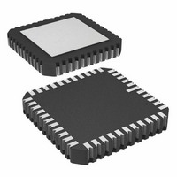
IC ADC 12BIT 10MSPS 44-CLCC
Manufacturer
Analog Devices Inc
Datasheet
1.AD872AJD.pdf
(20 pages)
Specifications of AD872AJE
Rohs Status
RoHS non-compliant
Number Of Bits
12
Sampling Rate (per Second)
10M
Data Interface
Parallel
Number Of Converters
7
Power Dissipation (max)
1.3W
Voltage Supply Source
Analog and Digital, Dual ±
Operating Temperature
0°C ~ 70°C
Mounting Type
Surface Mount
Package / Case
44-CLCC
Available stocks
Company
Part Number
Manufacturer
Quantity
Price


AD872A
Figure 12 shows the common-mode rejection performance vs.
frequency for a 1 V p-p common-mode input. This excellent
common-mode rejection over a wide bandwidth affords the user
the opportunity to eliminate many potential sources of input
noise as common mode by using the differential input structure
of the AD872A.
Figure 12. Common-Mode Rejection vs. Input Frequency,
1 V p-p Input
Figures 13 and 14 illustrate typical input connections for single-
ended inputs.
Figure 14. AD872A Single-Ended Input Connection Using
a Shielded Cable
The cable shield is used as a ground connection for the V
put, providing the best possible rejection of the cable noise from
the input signal. Note also that the high input impedance of the
AD872A allows the user to select the termination impedance, be
it 50 ohms, or some other value. Furthermore, unlike many
flash converters, most AD872A applications will not require an
external buffer amplifier. If such an amplifier is required, we
suggest either the AD811 or AD9617.
Figure 15 illustrates how external amplifiers may be used to
convert a single-ended input into a differential signal. The resis-
tor values of 536
mum phase matching between U1 and U2.
Figure 13. AD872A Single-Ended Input Connection
–100
–20
–30
–40
–50
–60
–70
–80
–90
10
1V
5
1V
and 562
INPUT FREQUENCY – Hz
10
6
1
2
were selected to provide opti-
R
T
V
V
INA
INB
1
2
AD872A
V
V
INA
INB
10
AD872A
7
10
INB
8
in-
–10–
Figure 15. Single-Ended to Differential Connections; U1,
U2 = AD811 or AD9617
The use of the differential input signal can help to minimize
even-order distortion from the input THA where performance
beyond –70 dB is desired.
Figure 16 shows the AD872A large signal (–0.5 dB) and small
signal (–20 dB) frequency response.
The AD872A’s wide input bandwidth facilitates rapid acquisi-
tion of transient input signals: the input THA can typically settle
to 12-bit accuracy from a full-scale input step in less than 40 ns.
Figure 17 illustrates the typical acquisition of a full-scale input
step.
Figure 16. Full Power (–0.5 dB) and Small Signal
Response (–20 dB) vs. Input Frequency
( 0.5V)
4500
4000
3500
3000
2500
2000
1500
1000
–10
–20
–30
–40
–50
500
10
Figure 17. Typical AD872A Settling Time
V
0
0
10
IN
0
4
10
562
536
10
20
5
INPUT FREQUENCY – Hz
30
U1
562
U2
536
nsec
10
40
6
50
V
V
INA
INB
10
60
7
AD872A
70
REV. A
10
80
8
Related parts for AD872AJE
Image
Part Number
Description
Manufacturer
Datasheet
Request
R

Part Number:
Description:
±1.7g Dual-Axis IMEMS Accelerometer Evaluation Board
Manufacturer:
Analog Devices Inc
Datasheet:

Part Number:
Description:
Inertial Sensor Evaluation System
Manufacturer:
Analog Devices Inc
Datasheet:
Part Number:
Description:
Manufacturer:
Analog Devices Inc
Datasheet:
Part Number:
Description:
Manufacturer:
Analog Devices Inc
Datasheet:
Part Number:
Description:
Manufacturer:
Analog Devices Inc
Datasheet:
Part Number:
Description:
Manufacturer:
Analog Devices Inc
Datasheet:
Part Number:
Description:
Manufacturer:
Analog Devices Inc
Datasheet:
Part Number:
Description:
Manufacturer:
Analog Devices Inc
Datasheet:
Part Number:
Description:
Manufacturer:
Analog Devices Inc
Datasheet:
Part Number:
Description:
Manufacturer:
Analog Devices Inc
Datasheet:
Part Number:
Description:
Manufacturer:
Analog Devices Inc
Datasheet:
Part Number:
Description:
Manufacturer:
Analog Devices Inc
Datasheet:
Part Number:
Description:
Manufacturer:
Analog Devices Inc
Datasheet: