AD679SD Analog Devices Inc, AD679SD Datasheet - Page 12
AD679SD
Manufacturer Part Number
AD679SD
Description
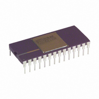
IC ADC 14BIT SAMPLING 28-CDIP
Manufacturer
Analog Devices Inc
Datasheet
1.AD679JNZ.pdf
(16 pages)
Specifications of AD679SD
Rohs Status
RoHS non-compliant
Number Of Bits
14
Sampling Rate (per Second)
128k
Data Interface
Parallel
Number Of Converters
2
Power Dissipation (max)
745mw
Voltage Supply Source
Analog and Digital, Dual ±
Operating Temperature
-55°C ~ 125°C
Mounting Type
Through Hole
Package / Case
28-CDIP (0.600", 15.24mm)
Available stocks
Company
Part Number
Manufacturer
Quantity
Price


AD679
INTERFACING THE AD679 TO MICROPROCESSORS
The I/O capabilities of the AD679 allow direct interfacing to
general-purpose and DSP microprocessor buses. The asynchro-
nous conversion control feature allows complete flexibility and
control with minimal external hardware.
The following examples illustrate typical AD679 interface
configurations.
AD679 to TMS320C25
In Figure 9, the AD679 is mapped into the TMS320C25 I/O
space. AD679 conversions are initiated by issuing an OUT
instruction to Port 1. EOC status and the conversion result are
read in with an IN instruction to Port 1. A single wait state is
inserted by generating the processor READY input from IS,
Port 1, and MSC. Address line A0 provides HBE decoding to
select between the high and low bytes of data. This configura-
tion supports processor clock speeds of 20 MHz and is capable
of supporting processor clock speeds of 40 MHz if a NOP instruc-
tion follows each AD679 read instruction.
AD679 to 80186
Figure 10 shows the AD679 interfaced to the 80186 micropro-
cessor. This interface allows the 80186’s built-in DMA control-
ler to transfer the AD679 output into a RAM based FIFO buffer
of any length, with no microprocessor intervention.
In this application the AD679 is configured in the asynchronous
mode, which allows conversions to be initiated by an external
trigger source independent of the microprocessor clock. After
each conversion, the AD679 EOC signal generates a DMA
request to Channel 1 (DRQ1). The subsequent DMA READ
sequences the high and low byte AD679 data and resets the
interrupt latch. The system designer must assign a sufficient
priority to the DMA channel to ensure that the DMA request is
serviced before the next conversion is completed. This configu-
ration can be used with 6 MHz and 8 MHz 80186
processors.
Figure 9. AD679 to TMS320C25 Interface
–12–
AD679 to Analog Devices ADSP-2101
Figure 11 demonstrates the AD679 interfaced to an ADSP-2101.
With a clock frequency of 12.5 MHz, and instruction execution in
one 80 ns cycle, the digital signal processor supports the AD679
interface with one wait state.
The converter is configured to run asynchronously using a sam-
pling clock. The EOC output of the AD679 gets asserted at the
end of each conversion and causes an interrupt. Upon interrupt,
the ADSP-2101 immediately asserts its FO pin LOW. In the
following cycle, the processor starts a data memory read by pro-
viding an address on the DMA bus. The decoded address gener-
ates OE for the converter, and the high byte of the conversion
result is read over the data bus. The read operation is extended
with one wait state and thus started and completed within two
processor cycles (160 ns). Next, the ADSP-2101 asserts its FO
HIGH. This allows the processor to start reading the lower byte
of data. This read operation executes in a similar manner to the
first and is completed during the next 160 ns.
Figure 10. AD679 to 80186 DMA Interface
Figure 11. AD679 to ADSP-2101 Interface
REV. D
Related parts for AD679SD
Image
Part Number
Description
Manufacturer
Datasheet
Request
R

Part Number:
Description:
±1.7g Dual-Axis IMEMS Accelerometer Evaluation Board
Manufacturer:
Analog Devices Inc
Datasheet:

Part Number:
Description:
Inertial Sensor Evaluation System
Manufacturer:
Analog Devices Inc
Datasheet:
Part Number:
Description:
Manufacturer:
Analog Devices Inc
Datasheet:
Part Number:
Description:
Manufacturer:
Analog Devices Inc
Datasheet:
Part Number:
Description:
Manufacturer:
Analog Devices Inc
Datasheet:
Part Number:
Description:
Manufacturer:
Analog Devices Inc
Datasheet:
Part Number:
Description:
Manufacturer:
Analog Devices Inc
Datasheet:
Part Number:
Description:
Manufacturer:
Analog Devices Inc
Datasheet:
Part Number:
Description:
Manufacturer:
Analog Devices Inc
Datasheet:
Part Number:
Description:
Manufacturer:
Analog Devices Inc
Datasheet:
Part Number:
Description:
Manufacturer:
Analog Devices Inc
Datasheet:
Part Number:
Description:
Manufacturer:
Analog Devices Inc
Datasheet:
Part Number:
Description:
Manufacturer:
Analog Devices Inc
Datasheet: