ADADC80-12 Analog Devices Inc, ADADC80-12 Datasheet - Page 8
ADADC80-12
Manufacturer Part Number
ADADC80-12
Description
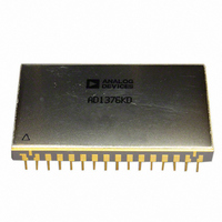
IC ADC 12-BIT INTEGRATED 32-CDIP
Manufacturer
Analog Devices Inc
Datasheet
1.ADADC80-12.pdf
(16 pages)
Specifications of ADADC80-12
Data Interface
Parallel
Rohs Status
RoHS non-compliant
Number Of Bits
12
Sampling Rate (per Second)
40k
Number Of Converters
1
Power Dissipation (max)
800mW
Voltage Supply Source
Analog and Digital, Dual ±
Operating Temperature
-25°C ~ 85°C
Mounting Type
Through Hole
Package / Case
32-CDIP (0.900", 22.86mm)
Resolution (bits)
12bit
Input Channel Type
Single Ended
Supply Current
70mA
Digital Ic Case Style
DIP
No. Of Pins
32
Operating Temperature Range
-25°C To +85°C
Number Of Elements
1
Resolution
12Bit
Architecture
SAR
Input Polarity
Unipolar/Bipolar
Input Type
Voltage
Rated Input Volt
5/10/±2.5/±5/±10V
Differential Input
No
Power Supply Requirement
Dual
Single Supply Voltage (typ)
Not RequiredV
Single Supply Voltage (min)
Not RequiredV
Single Supply Voltage (max)
Not RequiredV
Dual Supply Voltage (typ)
±15/5V
Dual Supply Voltage (min)
±14/4.75V
Dual Supply Voltage (max)
±16/5.25V
Differential Linearity Error
±0.5LSB(Typ)
Integral Nonlinearity Error
±0.012%FSR
Operating Temp Range
-25C to 85C
Operating Temperature Classification
Commercial
Mounting
Through Hole
Pin Count
32
Package Type
SBCDIP
Input Signal Type
Single-Ended
Lead Free Status / Rohs Status
Not Compliant
Available stocks
Company
Part Number
Manufacturer
Quantity
Price

Part Number:
ADADC80-12
Manufacturer:
AD
Quantity:
20 000


ADADC80
THEORY OF OPERATION
Upon receipt of a CONVERT START command, the ADADC80
converts the voltage at its analog input into an equivalent 12-bit
binary number. This conversion is accomplished as follows:
1.
2.
3.
TIMING
The timing diagram is shown in Figure 7. Receipt of a
CONVERT START signal sets the STATUS flag, indicating that
a conversion is in progress. This, in turn, removes the inhibit
applied to the gated clock, permitting it to run through 13 cycles.
The 12-bit successive-approximation register (SAR) has its
12-bit outputs connected both to the device bit output pins
and to the corresponding bit inputs of the feedback DAC.
The analog input is successively compared to the feedback
DAC output, one bit at a time (MSB first, LSB last).
The decision to keep or reject each bit is then made at the
completion of each bit comparison period, depending on
the state of the comparator at that time.
INTERNAL
CONVERT
STATUS
START
CLOCK
BIT 10
BIT 11
BIT 2
BIT 3
BIT 4
BIT 5
BIT 6
BIT 7
BIT 8
BIT 9
MSB
LSB
1
3
t
NOTES
1
1
2
3
*
0
THE CONVERT START PULSE WIDTH IS 100ns MINIMUM AND MUST REMAIN LOW DURING A CONVERSION.
THE CONVERSION IS INITIATED BY THE RISING EDGE OF THE CONVERT COMMAND.
25µs FOR 12 BITS AND 21µs FOR 10 BITS (MAXIMUM).
t
BIT DECISIONS.
1
SHOWS THE MSB DECISION AND
0
t
1
*
t
Figure 7. Timing Diagram (Binary Code 011001110110)
2
1
*
t
3
1
*
t
4
0
MAXIMUM THROUGHPUT TIME
t
CONVERSION TIME
Rev. E | Page 8 of 16
11
*
t
SHOWS THE LSB DECISION 40ns PRIOR TO THE STATUS GOING LOW.
5
0
*
t
6
1
All changes to the SAR parallel bit and to the STATUS bit are
initialized on the leading edge, and the gated clock inhibit
signal is removed on the trailing edge of the CONVERT START
signal. At time t
unconditionally. At t
BIT 2 is unconditionally reset. At t
(keep) and BIT 3 is reset unconditionally. This sequence
continues until the BIT 12 (LSB) decision (keep) is made at t
After a 40 ns delay period, the STATUS flag is reset, indicating
that the conversion is complete and the parallel output data is
valid. Resetting the STATUS flag restores the gated clock inhibit
signal, forcing the clock output to the Logic 0 state.
Parallel data bits become valid on the positive-going clock edge
(see Figure 7).
Incorporation of this 40 ns delay guarantees that the parallel
data is valid at the Logic l to Logic 0 transition of the STATUS
flag, permitting a parallel data transfer to be initiated by the
trailing edge of the STATUS signal.
*
t
2
7
1
*
t
8
1
*
t
9
0
0
, BIT 1 is reset and BIT 2 to BIT 12 are set
*
1
t
10
, the BIT 1 decision is made (keep) and
1
*
t
11
1
t
12
0
2
, the BIT 2 decision is made
12
.
Related parts for ADADC80-12
Image
Part Number
Description
Manufacturer
Datasheet
Request
R

Part Number:
Description:
IC ADC 12BIT INTEGRATED 32-CDIP
Manufacturer:
Analog Devices Inc
Datasheet:

Part Number:
Description:
±1.7g Dual-Axis IMEMS Accelerometer Evaluation Board
Manufacturer:
Analog Devices Inc
Datasheet:

Part Number:
Description:
Inertial Sensor Evaluation System
Manufacturer:
Analog Devices Inc
Datasheet:
Part Number:
Description:
Manufacturer:
Analog Devices Inc
Datasheet:
Part Number:
Description:
Manufacturer:
Analog Devices Inc
Datasheet:
Part Number:
Description:
Manufacturer:
Analog Devices Inc
Datasheet:
Part Number:
Description:
Manufacturer:
Analog Devices Inc
Datasheet:
Part Number:
Description:
Manufacturer:
Analog Devices Inc
Datasheet:
Part Number:
Description:
Manufacturer:
Analog Devices Inc
Datasheet:
Part Number:
Description:
Manufacturer:
Analog Devices Inc
Datasheet:
Part Number:
Description:
Manufacturer:
Analog Devices Inc
Datasheet:
Part Number:
Description:
Manufacturer:
Analog Devices Inc
Datasheet:
Part Number:
Description:
Manufacturer:
Analog Devices Inc
Datasheet: