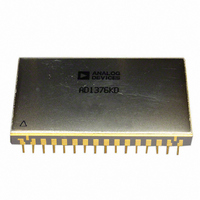
ADADC80-12 Analog Devices Inc, ADADC80-12 Datasheet - Page 2

ADADC80-12
Manufacturer Part Number
ADADC80-12
Description
IC ADC 12-BIT INTEGRATED 32-CDIP
Manufacturer
Analog Devices Inc
Datasheet
1.ADADC80-12.pdf
(16 pages)
Specifications of ADADC80-12
Data Interface
Parallel
Rohs Status
RoHS non-compliant
Number Of Bits
12
Sampling Rate (per Second)
40k
Number Of Converters
1
Power Dissipation (max)
800mW
Voltage Supply Source
Analog and Digital, Dual ±
Operating Temperature
-25°C ~ 85°C
Mounting Type
Through Hole
Package / Case
32-CDIP (0.900", 22.86mm)
Resolution (bits)
12bit
Input Channel Type
Single Ended
Supply Current
70mA
Digital Ic Case Style
DIP
No. Of Pins
32
Operating Temperature Range
-25°C To +85°C
Number Of Elements
1
Resolution
12Bit
Architecture
SAR
Input Polarity
Unipolar/Bipolar
Input Type
Voltage
Rated Input Volt
5/10/±2.5/±5/±10V
Differential Input
No
Power Supply Requirement
Dual
Single Supply Voltage (typ)
Not RequiredV
Single Supply Voltage (min)
Not RequiredV
Single Supply Voltage (max)
Not RequiredV
Dual Supply Voltage (typ)
±15/5V
Dual Supply Voltage (min)
±14/4.75V
Dual Supply Voltage (max)
±16/5.25V
Differential Linearity Error
±0.5LSB(Typ)
Integral Nonlinearity Error
±0.012%FSR
Operating Temp Range
-25C to 85C
Operating Temperature Classification
Commercial
Mounting
Through Hole
Pin Count
32
Package Type
SBCDIP
Input Signal Type
Single-Ended
Lead Free Status / Rohs Status
Not Compliant
Available stocks
Company
Part Number
Manufacturer
Quantity
Price
Part Number:
ADADC80-12
Manufacturer:
AD
Quantity:
20 000
ADADC80
TABLE OF CONTENTS
Features .............................................................................................. 1
Functional Block Diagram .............................................................. 1
Product Description ......................................................................... 1
Product Highlights ........................................................................... 1
Revision History ............................................................................... 2
Specifications ..................................................................................... 3
Absolute Maximum Ratings ............................................................ 5
Pin Configuration and Function Descriptions ............................. 6
Typical Performance Characteristics ............................................. 7
Theory of Operation ........................................................................ 8
REVISION HISTORY
2/08—Rev. D to Rev. E
Updated Format .................................................................. Universal
Pin 7 Changed to NC ......................................................... Universal
Changes to Specifications Section .................................................. 3
Added Absolute Maximum Ratings Section ................................. 5
Updated Outline Dimensions ....................................................... 13
Changes to Ordering Guide .......................................................... 13
ESD Caution .................................................................................. 5
Rev. E | Page 2 of 16
Outline Dimensions ....................................................................... 14
8/03—Rev. C to Rev. D
Changes to Specifications ................................................................. 2
4/03—Rev. B to Rev. C
Changes to General Description ..................................................... 1
9/02—Rev. A to Rev. B
Changes to Figure 1 ........................................................................... 6
Updated Outline Dimensions ....................................................... 11
Timing ............................................................................................8
Digital Output Data ......................................................................9
Input Scaling ..................................................................................9
Offset Adjustment ...................................................................... 10
Gain Adjustment ........................................................................ 10
Calibration ................................................................................... 11
Grounding ................................................................................... 12
Control Modes ............................................................................ 13
Ordering Guide .......................................................................... 14


