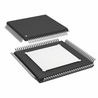
AD9271BSVZ-25 Analog Devices Inc, AD9271BSVZ-25 Datasheet - Page 24

AD9271BSVZ-25
Manufacturer Part Number
AD9271BSVZ-25
Description
IC ADC OCT 12BIT 25MSPS 100-TQFP
Manufacturer
Analog Devices Inc
Datasheet
1.AD9271BSVZ-50.pdf
(60 pages)
Specifications of AD9271BSVZ-25
Data Interface
Serial, SPI™
Number Of Bits
12
Sampling Rate (per Second)
25M
Number Of Converters
8
Power Dissipation (max)
1.06W
Voltage Supply Source
Single Supply
Operating Temperature
-40°C ~ 85°C
Mounting Type
Surface Mount
Package / Case
100-TQFP Exposed Pad
Resolution (bits)
12bit
Sampling Rate
50MSPS
Input Channel Type
Differential, Single Ended
Supply Voltage Range - Digital
1.7V To 1.9V
Supply Current
505mA
Lead Free Status / RoHS Status
Lead free / RoHS Compliant
For Use With
AD9271-50EBZ - BOARD EVALUATION AD9271 50MSPS
Lead Free Status / RoHS Status
Lead free / RoHS Compliant, Lead free / RoHS Compliant
Available stocks
Company
Part Number
Manufacturer
Quantity
Price
Company:
Part Number:
AD9271BSVZ-25
Manufacturer:
AD
Quantity:
1 600
Company:
Part Number:
AD9271BSVZ-25
Manufacturer:
Analog Devices Inc
Quantity:
10 000
AD9271
CW DOPPLER OPERATION
Modern ultrasound machines used for medical applications
employ a 2
typical array sizes of 16 or 32 receiver channels phase-shifted
and summed together to extract coherent information. When
used in multiples, the desired signals from each channel can be
summed to yield a larger signal (increased by a factor N, where
N is the number of channels), and the noise is increased by the
square root of the number of channels. This technique enhances
the signal-to-noise performance of the machine. The critical
elements in a beam-former design are the means to align the
incoming signals in the time domain and the means to sum the
individual signals into a composite whole.
Beam forming, as applied to medical ultrasound, is defined as the
phase alignment and summation of signals that are generated
from a common source but received at different times by a
multielement ultrasound transducer. Beam forming has two
functions: it imparts directivity to the transducer, enhancing its
N
binary array of receivers for beam forming, with
8 × CHANNEL
8 × CHANNEL
LNA
LNA
LNA
LNA
LNA
LNA
LNA
LNA
AD9271
AD9271
g
g
g
g
g
g
g
g
m
m
m
m
m
m
m
m
Figure 47. Typical CW Doppler System Using the AD9271 and AD8333 or AD8339
SWITCH
SWITCH
ARRAY
ARRAY
Rev. B | Page 24 of 60
2.5V
2.5V
2.5V
2.5V
600nH
600nH
600nH
600nH
600nH
600nH
600nH
600nH
gain, and it defines a focal point within the body from which the
location of the returning echo is derived.
The AD9271 includes the front-end components needed to
implement analog beam forming for CW Doppler operation.
These components allow CW channels with similar phases to be
coherently combined before phase alignment and down mixing,
thus reducing the number of delay lines or adjustable phase shifters/
down mixers
are used, the phase alignment is performed and then the channels
are coherently summed and down converted by a dynamic range
I/Q demodulator. Alternatively, if phase shifters/down mixers,
such as the AD8333 and AD8339, are used, phase alignment
and downconversion are done before coherently summing all
channels into I/Q signals. In either case, the resultant I and Q
signals are filtered and sampled by two high resolution ADCs,
and the sampled signals are processed to extract the relevant
Doppler information.
700Ω
700Ω
700Ω
700Ω
AD8333
AD8333
(AD8333
Q
I
or AD8339) required. Next, if delay lines
16-BIT
16-BIT
ADC
ADC


