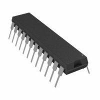
AD7731BNZ Analog Devices Inc, AD7731BNZ Datasheet - Page 39

AD7731BNZ
Manufacturer Part Number
AD7731BNZ
Description
IC ADC 24BIT SIGMA-DELTA 24DIP
Manufacturer
Analog Devices Inc
Datasheet
1.AD7731BRUZ.pdf
(44 pages)
Specifications of AD7731BNZ
Data Interface
DSP, Serial, SPI™
Number Of Bits
24
Sampling Rate (per Second)
6.4k
Number Of Converters
1
Power Dissipation (max)
125mW
Voltage Supply Source
Analog and Digital
Operating Temperature
-40°C ~ 85°C
Mounting Type
Through Hole
Package / Case
24-DIP (0.300", 7.62mm)
Resolution (bits)
24bit
Sampling Rate
6.4kSPS
Input Channel Type
Single Ended
Supply Voltage Range - Analog
4.75V To 5.25V
Supply Voltage Range - Digital
2.7V To 5.25V
Lead Free Status / RoHS Status
Lead free / RoHS Compliant
For Use With
EVAL-AD7731EBZ - BOARD EVALUATION FOR AD7731
Lead Free Status / RoHS Status
Lead free / RoHS Compliant, Lead free / RoHS Compliant
REV. A
APPLICATIONS
The on-chip PGA allows the AD7731 to handle analog input
voltage ranges from 20 mV to 1.28 V. This makes the AD7731
suitable for a range of application areas from handling signals
directly from a transducer to processing fully-conditioned full-
scale inputs. Some of these applications are discussed in the
following sections.
The AD7731 offers both unipolar and bipolar input ranges. In
many cases, the application is single supply with the bipolar
input voltages referenced to a biased-up differential voltage.
Some applications will, however, require the flexibility of han-
dling true bipolar inputs. Figure 25 shows how to configure the
AD7731 to handle this type of signal.
It should be noted in multiplexed applications that an input
overvoltage (either >AVDD + 0.3 V or <AGND – 0.3 V) on an
unselected channel can affect the conversion result on the se-
lected channel. The system design should ensure that the input
voltage on channels where input leads may be unconnected or
broken be kept within the above limits.
The AD7731 has a variety of different modes aimed at optimiz-
ing the AD7731’s performance across differing application require-
ments. The issue of filtering and settling time and throughput rates
in multichannel applications has previously been discussed in the
Filter Architecture section.
REV. 0
IN1+
IN2+
IN3+
IN1–
IN2–
IN3–
+V
AD780
IN
GND
+5V
V
OUT
REF IN (+)
REF IN (–)
AGND
AIN1
AIN2
AIN3
AIN4
AIN5
AIN6
Figure 21. Data Acquisition Using the AD7731
AGND
AV
DD
DGND
100nA
100nA
+5V
AV
BUFFER
DD
AND CONTROL LOGIC
PGA
SERIAL INTERFACE
DV
DD
–39–
DOUT
MICROCONTROLLER
REGISTER BANK
Data Acquisition
The AD7731 with its three differential channels (or five pseudo-
differential channels) is suited to low bandwidth, high resolution
data acquisition systems. In addition, the three-wire digital
interface allows this data acquisition front end to be isolated
with just three optoisolators. The entire system can be operated
from a single +5 V supply provided that the input signals to the
AD7731’s analog inputs are all of positive polarity. Figure 21
shows the AD7731 in an isolated three-channel data acquisition
system.
Programmable Logic Controllers
The AD7731 is also suited to programmable logic controller
applications. In such applications, the ADC is required to
handle signals from a variety of different transducers. The
AD7731’s programmable gain front end allows the part to either
handle low level signals directly from a transducer or full-scale
signals which have already been conditioned. The fast through-
put rate and settling-time of the part is also an important feature
in these applications where loop response time is often critical.
The configuration of the AD7731 in PLC applications is similar
to that outlined in Figure 21 for the data acquisition system.
MODULATOR
SIGMA-
DELTA
DIN
SIGMA-DELTA A/D
AD7731
CONVERTER
CS
GENERATION
CLOCK
DIGITAL
FILTER
SCLK
OPTO-ISOLATORS
MCLK IN
MCLK OUT
STANDBY
SYNC
POL
RESET
RDY
AD7731


