AD7575AQ Analog Devices Inc, AD7575AQ Datasheet - Page 2
AD7575AQ
Manufacturer Part Number
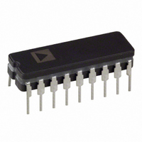
AD7575AQ
Description
IC ADC 8BIT LC2MOS W/HOLD 18CDIP
Manufacturer
Analog Devices Inc
Datasheet
1.AD7575JPZ-REEL.pdf
(12 pages)
Specifications of AD7575AQ
Rohs Status
RoHS non-compliant
Number Of Bits
8
Sampling Rate (per Second)
50k
Data Interface
Parallel
Number Of Converters
1
Power Dissipation (max)
15mW
Voltage Supply Source
Single Supply
Operating Temperature
-25°C ~ 85°C
Mounting Type
Through Hole
Package / Case
18-CDIP (0.300", 7.62mm)


Parameter
ACCURACY
ANALOG INPUT
REFERENCE INPUT
LOGIC INPUTS
CLK
LOGIC OUTPUTS
CONVERSION TIME
POWER REQUIREMENTS
NOTES
1
2
3
4
5
Specifications subject to change without notice.
AD7575–SPECIFICATIONS
Temperature ranges are as follows:
Offset error is measured with respect to an ideal first code transition that occurs at 1/2 LSB.
Sample tested at +25 C to ensure compliance.
Accuracy may degrade at conversion times other than those specified.
Power supply current is measured when AD7575 is inactive i.e., when CS = RD = BUSY = logic HIGH.
Resolution
Total Unadjusted Error
Relative Accuracy
Minimum Resolution for Which
Full-Scale Error
Offset Error
Voltage Range
DC Input Impedance
Slew Rate, Tracking
SNR
V
I
CS, RD
C
V
V
I
I
BUSY, DB0 to DB7
DB0 to DB7
With External Clock
With Internal Clock, T
V
I
Power Dissipation
Power Supply Rejection
REF
INL
INH
DD
REF
lNL
INH
DD
IN
Floating State Output Capacitance
No Missing Codes Is Guaranteed
+25 C
T
+25 C
T
V
V
I
+25 C
T
V
V
Floating State Leakage Current
J, K Versions; 0 C to +70 C
A, B Versions; –25 C to +85 C
S, T Versions; –55 C to +125 C
IN
, Input Capacitance
INL
INH
, Input Low Current
OL
OH
MIN
MIN
MIN
, Input High Current
, Input Low Voltage
, Input High Voltage
3
, Input Current
(For Specified Performance)
, Output Low Voltage
, Output High Voltage
, Input Low Voltage
, Input High Voltage
to T
to T
to T
2
MAX
MAX
MAX
4
A
3
= +25 C
5
3
J, A Versions
8
8
0 to 2 V
10
0.386
45
1.23
500
0.8
2.4
10
0.8
2.4
700
700
0.4
4.0
10
5
5
15
+5
6
15
2
1
1
1
1/2
1/2
1
10
1
1/4
REF
1
K, B Versions
8
8
0 to 2 V
10
45
500
0.8
2.4
10
0.8
2.4
0.4
4.0
10
5
5
15
+5
6
15
0.386
1.23
700
700
1
1/2
1
1
1/2
1/2
1
10
1
1/4
(V
all specifications T
DD
REF
= +5 V, V
8
8
45
10
10
S Version
0 to 2 V
10
0.386
1.23
500
0.8
2.4
0.8
2.4
800
800
0.4
4.0
5
5
15
+5
7
15
–2–
2
1
1
1
1/2
1/2
1
10
10
1/4
REF
= +1.23 V, AGND = DGND = 0 V; f
MIN
REF
to T
T Version
8
8
0 to 2 V
10
0.386
45
1.23
500
0.8
2.4
10
0.8
2.4
800
800
0.4
4.0
10
5
5
15
+5
7
15
1
1/2
1
1
1/2
1/2
1
10
10
1/4
MAX
unless otherwise noted)
REF
Units
Bits
LSB max
LSB max
Bits max
LSB max
LSB max
LSB max
LSB max
Volts
M min
V/ s max
dB min
Volts
V max
V min
pF max
V max
V min
V max
V min
pF max
Volts
mA max
mW typ
LSB max
A max
A max
A max
A max
A max
A max
s
s min
s max
Full-Scale TC Is Typically 5 ppm/ C
Offset TC Is Typically 5 ppm/ C
1 LSB = 2 V
V
V
V
V
I
I
V
f
Using Recommended Clock
Typically 3 mA with V
4.75 V
Conditions/Comments
V
Components Shown in Figure 15
CLK
SINK
SOURCE
IN
5%
IN
IN
INL
INH
OUT
5% for Specified Performance
CLK
= 2.46 V p-p @ 10 kHz; See Figure 11
= 0 or V
= 0 or V
= 4 MHz
= 0 V
= V
= 4 MHz external;
= 1.6 mA
= 0 to V
= 40 A
DD
V
DD
REF
DD
DD
DD
/256; See Figure 16
5.25 V
DD
= +5 V
REV. B
Related parts for AD7575AQ
Image
Part Number
Description
Manufacturer
Datasheet
Request
R

Part Number:
Description:
±1.7g Dual-Axis IMEMS Accelerometer Evaluation Board
Manufacturer:
Analog Devices Inc
Datasheet:

Part Number:
Description:
Inertial Sensor Evaluation System
Manufacturer:
Analog Devices Inc
Datasheet:
Part Number:
Description:
Manufacturer:
Analog Devices Inc
Datasheet:
Part Number:
Description:
Manufacturer:
Analog Devices Inc
Datasheet:
Part Number:
Description:
Manufacturer:
Analog Devices Inc
Datasheet:
Part Number:
Description:
Manufacturer:
Analog Devices Inc
Datasheet:
Part Number:
Description:
Manufacturer:
Analog Devices Inc
Datasheet:
Part Number:
Description:
Manufacturer:
Analog Devices Inc
Datasheet:
Part Number:
Description:
Manufacturer:
Analog Devices Inc
Datasheet:
Part Number:
Description:
Manufacturer:
Analog Devices Inc
Datasheet:
Part Number:
Description:
Manufacturer:
Analog Devices Inc
Datasheet:
Part Number:
Description:
Manufacturer:
Analog Devices Inc
Datasheet:
Part Number:
Description:
Manufacturer:
Analog Devices Inc
Datasheet: