4-647010-5 TE Connectivity, 4-647010-5 Datasheet

15P MTA100 PSTD CONN ASSY LF

4-647010-5

Manufacturer Part Number
4-647010-5
Description
15P MTA100 PSTD CONN ASSY LF
Manufacturer
TE Connectivity
Datasheets

Specifications of 4-647010-5

Connector Type
Connector Assembly
Connector Design
Closed End
Product Line
MTA-100
Termination Method To Wire/cable
IDC Standard
Wire Size (mm² [awg])
0.12-0.15² [26]
Mating Connector Lock
Without
Four Points Of Contact
Without
Shrouded
No
Mounting Ears
Without
Panel Mount Retention
Without
Voltage Rating (vac)
250
Solder Tail Contact Plating
Bright Tin
Number Of Positions
5
Centerline (mm [in])
2.54 [0.100]
Narrow
No
Post Number(s) Omitted
None
Contact Type
Socket
Contact Plating, Mating Area, Material
Gold (30) or (30) Total Gold Flash over Palladium Nickel
Contact Base Material
Copper Alloy
Connector Style
Receptacle
Housing Color
Blue
Mating Alignment
Without
Ul Flammability Rating
UL 94V-2
Housing Material
Nylon
Rohs/elv Compliance
RoHS compliant, ELV compliant
Lead Free Solder Processes
Not relevant for lead free process
Rohs/elv Compliance History
Always was RoHS compliant
Applies To
Wire/Cable
Application Use
Wire-to-Wire
1.
1.1.
1.2.
1.3.
2.
2.1.
2.2.
3.
3.1.
©2011 Tyco Electronics Corporation,
a TE Connectivity Ltd. Company
All Rights Reserved
TE logo is a trademark.
SCOPE
Content
This specification covers the performance, tests and quality requirements for the TE Connectivity (TE)
MTA-100 posted connector wire-to-wire system. This system is mass terminated using insulation
displacement technology on 2.54 mm [.100 in] centerlines and mates with standard MTA connectors,
providing a reliable interconnection between wires in wire-to-wire applications. The system is available
in 2 through 17 positions. The MTA-100 connector wire-to-wire system is designed to be terminated to
tin plated wire 28 AWG through 22 AWG, UL style 1007, 1061, or wire which specifies PVC insulation
with temperature rating compatible with specified operating temperatures per Figure 4. Wire shall meet
application requirements specified in Application Specification 114-1019. Insulation diameters are: 1.27
mm [.050 in] maximum outside diameter for mass termination and 1.52 mm [.060 in] maximum outside
diameter for single termination.
Qualification
When tests are performed on the subject product line, procedures specified in Figure 1 shall be used.
All inspections shall be performed using the applicable inspection plan and product drawing.
Qualification Test Results
Successful qualification testing on the subject product line was completed on 25Mar99. The
Qualification Test Report number for this testing is 501-366-1. This documentation is on file at and
available from Engineering Practices and Standards (EPS).
APPLICABLE DOCUMENTS
The following documents form a part of this specification to the extent specified herein. Unless
otherwise specified, the latest edition of the document applies. In the event of conflict between the
requirements of this specification and the product drawing, the product drawing shall take precedence.
In the event of conflict between the requirements of this specification and the referenced documents,
this specification shall take precedence.
TE Connectivity (TE) Documents
!
!
!
!
Reference Document
108-1050: Product Specification (Connector, MTA-100)
REQUIREMENTS
Design and Construction
Product shall be of the design, construction and physical dimensions specified on the applicable product
drawing.
109-1: Test Specification (General Requirements for Test Specifications)
109 Series: Test Specifications as indicated in Figure 1
114-1019: Application Specification (MTA 100 Connector Assemblies (English And Spanish))
501-366-1: Qualification Test Report (MTA-100 Wire-To-Wire Posted Connector System)
| Indicates change
*Trademark
Product
Specification
MTA-100 Wire-To-Wire Posted Connector System
For latest revision, visit our website at www.te.com/documents.
For Regional Customer Service, visit our website at www.te.com
Other products, logos, and company names might be trademarks of their respective owners.
108-1050-1
11Mar11 Rev D
1 of 11
LOC B

Related parts for 4-647010-5

4-647010-5 Summary of contents

Page 1

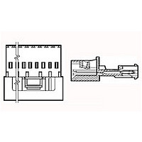
... This specification covers the performance, tests and quality requirements for the TE Connectivity (TE) MTA-100 posted connector wire-to-wire system. This system is mass terminated using insulation displacement technology on 2.54 mm [.100 in] centerlines and mates with standard MTA connectors, providing a reliable interconnection between wires in wire-to-wire applications. The system is available in 2 through 17 positions ...

Page 2

... Materials used in the construction of this product shall be as specified on the applicable product drawing. 3.3. Ratings ! Voltage: 250 volts AC ! Current: See Figure 4 for applicable current carrying capability ! Temperature: -55 to 105° C 3.4. Performance and Test Description Product is designed to meet the electrical, mechanical and environmental performance requirements specified in Figure 1 ...

Page 3

... ENVIRONMENTAL See Note. Figure 1 (continued) 108-1050-1 Procedure TE Spec 109-16. Determine slot tensile at a maximum rate of 25 in] per minute. See Figure 5. TE Spec 109-21-1. Subject mated samples to 10-55-10 Hz traversed in 1 minute at 1.5 mm [0.06 inch] total excursion. Two hours in each of 3 mutually perpendicular planes ...

Page 4

... C at 95% RH with vibration and cold shock. TE Spec 109-43. Subject mated samples to temperature life at 105° C for gold plated samples and 85° C for tin plated samples for 1000 hours. TE Spec 109-85-3. Subject mated samples to environmental class III for 20 days ...

Page 5

... Mating force Unmating force Thermal shock Humidity/temperature cycling Temperature life Mixed flowing gas (a) See paragraph 4.1.A. NOTE (b) Numbers indicate sequence in which tests are performed. (c) Tin-lead plated samples. (d) Gold plated samples. (e) Subject half the samples to parallel tensile test and the other half to perpendicular tensile test for a total of 30 pulls with each wire size ...

Page 6

... AWG wire and 3, 16 position tin-lead plated samples terminated with 12 inch lengths of 28 AWG wire. Test group 3 shall consist of 5 mated, 16 position gold plated samples terminated with 22 AWG wire. Test group 4 shall consist of 5 mated, 8 position tin-lead plated samples terminated with 22 AWG wire. Test group 5 shall consist of 5 pieces each of 16 position tin-lead plated samples in each wire gage ...

Page 7

Termination resistance equals millivolts divided by test current less resistance of twice the NOTE length of wire used for “A” dimension. (b) After soldering, boards and solder joints shall be cleaned to remove all flux and contaminants. Temperature & ...

Page 8

... Multiplication Factor (F) from the above chart and multiply it times the Base rated Current for a single circuit at maximum ambient operating temperature as shown in Figure 4A. The F-Factor for the 50% loading condition is based on temperature rise data where every other (odd positions) was energized. The F-Factor will change if different positions are energized since the loading density calculation would be different ...

Page 9

Rev D Figure 5 Termination Tensile Strength 108-1050 ...

Page 10

Rev D Figure 6 Vibration & Physical Shock Mounting Fixture 108-1050 ...

Page 11

Rev D Figure 7 Printed Circuit Test Board 108-1050 ...

Related keywords