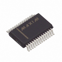
MAX1401EAI+ Maxim Integrated Products, MAX1401EAI+ Datasheet - Page 3

MAX1401EAI+
Manufacturer Part Number
MAX1401EAI+
Description
IC ADC 18BIT LP 28-SSOP
Manufacturer
Maxim Integrated Products
Datasheet
1.MAX1401EAI.pdf
(36 pages)
Specifications of MAX1401EAI+
Number Of Bits
18
Sampling Rate (per Second)
480
Data Interface
QSPI™, Serial, SPI™
Number Of Converters
1
Power Dissipation (max)
750µW
Voltage Supply Source
Analog and Digital
Operating Temperature
-40°C ~ 85°C
Mounting Type
Surface Mount
Package / Case
28-SSOP
Number Of Adc Inputs
5
Architecture
Delta-Sigma
Conversion Rate
4.8 KSPs
Resolution
18 bit
Input Type
Voltage
Interface Type
Serial
Voltage Reference
External
Supply Voltage (max)
3 V
Maximum Power Dissipation
21.45 mW
Maximum Operating Temperature
+ 85 C
Mounting Style
SMD/SMT
Input Signal Type
Pseudo-Differential, Differential
Minimum Operating Temperature
- 40 C
Lead Free Status / RoHS Status
Lead free / RoHS Compliant
ELECTRICAL CHARACTERISTICS (continued)
(V+ = +2.7V to +3.6V, V
otherwise noted. Typical values are at T
OFFSET DAC
ANALOG INPUTS/REFERENCE INPUTS (Specifications for AIN and REFIN, unless otherwise noted.)
Offset DAC Range (Note 8)
Offset DAC Resolution
Offset DAC Full-Scale Error
Offset DAC Zero-Scale Error
Additional Noise from Offset
DAC (Note 9)
Common-Mode Rejection
Normal-Mode 50Hz Rejection
(Note 10)
Normal-Mode 60Hz Rejection
(Note 10)
Common-Mode Voltage Range
(Note 11)
Absolute Input Voltage Range
Absolute and Common-Mode
AIN Voltage Range
DC Input Leakage Current
(Note 12)
AIN Input Current (Note 12)
AIN Input Capacitance
(Note 13)
AIN Differential Voltage Range
(Note 14)
PARAMETER
________________________________________________________________________________________
DD
= +2.7V to +3.6V, V
+3V, 18-Bit, Low-Power, Multichannel,
SYMBOL
CMR
NMR
NMR
A
= +25°C.)
Oversampling (Sigma-Delta) ADC
For filter notch 50Hz, ±0.02
MF1 = 0, MF0 = 0, f
Unipolar mode
Bipolar mode
Unipolar mode
Bipolar mode
Input referred
DAC code = 0000
At DC
For filter notch 60Hz, ±0.02
MF1 = 0, MF0 = 0, f
For filter notch 50Hz, ±0.02
MF1 = 0, MF0 = 0, f
For filter notch 60Hz, ±0.02
MF1 = 0, MF0 = 0, f
REFIN and AIN for BUFF = 0
REFIN and AIN for BUFF = 0
BUFF = 1
REFIN and AIN for
BUFF = 0
BUFF = 1
BUFF = 0
BUFF = 1, all gains
Unipolar input range (U/B bit = 1)
Bipolar input range (U/B bit = 0)
REFIN+
= +1.25V, REFIN- = AGND, f
CONDITIONS
Gain = 1, 2, 4, 8, 16, 32, 64
Inp
Gain = 128
CLKIN
CLKIN
CLKIN
CLKIN
= 2.4576MHz (Note 10)
= 2.4576MHz (Note 10)
T
T
Gain = 1
Gain = 2
Gain = 4
Gain = 8, 16, 32, 64, 128
A
A
·
·
= 2.4576MHz
= 2.4576MHz
f
f
= +25°C
= T
NOTCH
NOTCH
·
·
f
f
NOTCH
NOTCH
MIN
,
,
to T
,
,
CLKIN
MAX
= 2.4576MHz, T
+ 200mV
V
V
- 30mV
V
-116.7
-58.35
MIN
AGND
AGND
AGND
-2.5
-3.5
150
150
100
100
90
0 to V
±V
REF
TYP
16.7
8.35
REF
A
40
34
38
45
60
30
0
0
= T
/ gain
/ gain
MIN
+ 30mV
116.7
58.35
MAX
- 1.5
V+
2.5
3.5
to T
V+
V+
10
10
MAX
UNITS
µV
%FSR
%FSR
%FSR
%FSR
, unless
dB
dB
dB
pA
nA
nA
pF
RMS
V
V
V
V
3


