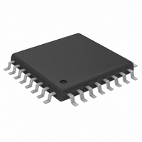
MAX1498ECJ+ Maxim Integrated Products, MAX1498ECJ+ Datasheet - Page 5

MAX1498ECJ+
Manufacturer Part Number
MAX1498ECJ+
Description
IC ADC 4 1/2DIG W/LED DVR 32TQFP
Manufacturer
Maxim Integrated Products
Datasheet
1.MAX1496EAI.pdf
(24 pages)
Specifications of MAX1498ECJ+
Number Of Bits
4.5 Digit
Sampling Rate (per Second)
5
Number Of Converters
1
Power Dissipation (max)
1.65W
Voltage Supply Source
Analog and Digital
Operating Temperature
-40°C ~ 85°C
Mounting Type
Surface Mount
Package / Case
32-LQFP
Lead Free Status / RoHS Status
Lead free / RoHS Compliant
ELECTRICAL CHARACTERISTICS (continued)
(AV
C
Typical values are at T
Note 1: Integral nonlinearity is the deviation of the analog value at any code from its theoretical value after nulling the gain error and
Note 2: Offset calibrated.
Note 3: Offset nulled.
Note 4: Drift error is eliminated by recalibration at the new temperature.
Note 5: The input voltage range for the analog inputs is given with respect to the voltage on the negative input of the differential pair.
Note 6: V
Note 7: Power-supply currents are measured with all digital inputs at either GND or DV
Note 8: Measured at DC by changing the power-supply voltage from 2.7V to 5.25V and measuring the effect on the conversion
Note 9: LED drivers are disabled.
LED DRIVERS (Table 5)
LED Supply Voltage
LED Shutdown Supply Current
LED Supply Current
Display Scan Rate
Segment Current Slew Rate
DIG_ Voltage Low
Segment Drive Source Current
Matching
Segment Drive Source Current
Interdigit Blanking Time
REF+
DD
= DV
= C
offset error.
AIN+ and REF+ only.
error with external reference. PSRR at 50Hz and 60Hz exceeds 120dB with filter notches at 50Hz and 60Hz (Figure 2).
AIN
REF-
PARAMETER
DD
+ or V
= V
= 0.1µF, C
DD
AIN
_______________________________________________________________________________________
= +2.7V to +5.25V, GND = 0, V
A
- = -2.2V to +2.2V. V
= +25°C, unless otherwise noted.)
VNEG
= 0.1µF. Internal clock mode, unless otherwise noted. All specifications are at T
3.5- and 4.5-Digit, Single-Chip ADCs
SYMBOL
∆I
I
∆I
V
SHDN
f
V
SEG
I
I
OSC
SEG
LED
LED
DIG
SEG
REF
/∆t
+ or V
LED driver shutdown mode
Seven segments and decimal point on,
R
MAX1447/MAX1498
MAX1496
I
V
DIG_
LED
ISET
REF
LED
= 176mA
- V
= 25kΩ
- = -2.2V to +2.2V. All input structures are identical. Production tested on
SEG
= +2.7V to +5.25V, GLED = 0, V
= 0.6V, R
CONDITIONS
ISET
= 25kΩ
with LED Drivers
DD
REF+
.
- V
MIN
2.70
16.0
REF-
= 2.048V (external reference),
0.178
TYP
21.5
176
512
640
25
3
4
A
0.300
MAX
5.25
25.5
±10
180
= T
10
MIN
to T
UNITS
mA/µs
mA
mA
µA
Hz
µs
%
V
V
MAX
5
.


