LMX2336USLBX National Semiconductor, LMX2336USLBX Datasheet - Page 41
LMX2336USLBX
Manufacturer Part Number
LMX2336USLBX
Description
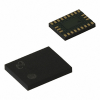
IC FREQ SYNTH DUAL 24LAMINATECSP
Manufacturer
National Semiconductor
Series
PLLatinum™r
Type
PLL Frequency Synthesizerr
Datasheet
1.LMX2335UTMNOPB.pdf
(48 pages)
Specifications of LMX2336USLBX
Pll
Yes with Bypass
Input
CMOS, TTL
Output
CMOS
Number Of Circuits
1
Ratio - Input:output
3:1
Differential - Input:output
Yes/No
Frequency - Max
2GHz, 1.2GHz
Divider/multiplier
Yes/No
Voltage - Supply
2.7 V ~ 5.5 V
Operating Temperature
-40°C ~ 85°C
Mounting Type
Surface Mount
Package / Case
24-Laminate CSP
Frequency-max
2GHz
Lead Free Status / RoHS Status
Contains lead / RoHS non-compliant
Other names
LMX2336USLBXTR


Reg. Most Significant Bit
RF1
Divide Ratio
N
Divide
Ratio
2.0 Programming Description
2.6.3 ID
The ID
2.6.4 TRI-STATE ID
The TRI-STATE ID
output state. This happens asynchronously with the change in the TRI-STATE ID
Furthermore, the TRI-STATE ID
powerdown mode.
2.7 RF1 N REGISTER
The RF1 N register contains the RF1 N_CNTRA, RF1 N_CNTRB, PRE RF1, and PWDN RF1 control words. The RF1 N_CNTRA
and RF1 N_CNTRB control words are used to setup the programmable feedback divider. The detailed description and
programming information for each control word is discussed in the following sections.
2.7.1 RF1 N_CNTRA[6:0]
The RF1 N_CNTRA control word is used to setup the RF1 synthesizer’s A counter. The A counter is a 7-bit swallow counter used
in the programmable feedback divider. The RF1 N_CNTRA control word can be programmed to values ranging from 0 to 127.
2.7.2 RF1 N_CNTRB[10:0]
The RF1 N_CNTRB control word is used to setup the RF1 synthesizer’s B counter. The B counter is an 11-bit programmable
binary counter used in the programmable feedback divider. The RF1 N_CNTRB control word can be programmed to values
ranging from 3 to 2047.
2047
TRI-STATE ID
3
4
•
PWDN
127
RF1
Control Bit
Control Bit
21
0
1
•
ID
o
o
o
RF1 bit controls the RF1 synthesizer’s charge pump gain. Two current levels are available.
PRE
RF1
RF1
RF1
20
10
0
0
1
•
o
19
RF1
o
o
RF1 bit allows the charge pump to be switched between a normal operating mode and a high impedance
6
0
0
1
•
18
RF1
9
0
0
1
•
Register Location
Register Location
17
RF1 SYNTHESIZER CHARGE PUMP CURRENT GAIN
RF1 SYNTHESIZER CHARGE PUMP TRI-STATE CURRENT
RF1 SYNTHESIZER SWALLOW COUNTER (A COUNTER)
o
RF1 R[18]
RF1 R[19]
RF1 SYNTHESIZER PROGRAMMABLE BINARY COUNTER (B COUNTER)
RF1 N_CNTRB[10:0]
RF1 bit operates in conjuction with the PWDN RF1 bit to set a synchronous or an asynchronous
16
8
0
0
1
•
5
0
0
1
•
15
14
7
0
0
1
•
13
SHIFT REGISTER BIT LOCATION
(Continued)
RF1 Charge Pump
Current Gain
RF1 Charge Pump
TRI-STATE Current
4
0
0
1
•
Data Field
12
Description
Description
6
0
0
1
•
RF1 N_CNTRB[10:0]
RF1 N_CNTRA[6:0]
11
41
10
5
0
0
1
•
3
0
0
1
•
9
RF1 Charge Pump
Normal Operation
4
0
0
1
•
8
o
RF1 bit.
0.95 mA
7
LOW
2
0
0
1
•
RF1 N_CNTRA[6:0]
0
0
3
0
0
1
•
6
5
Function
Function
2
0
1
1
•
4
1
0
0
1
•
RF1 Charge Pump
Output in High
Impedance State
Least Significant Bit
3
3.80 mA
1
1
0
1
•
HIGH
RF1 N[9:19]
RF1 N[2:8]
2
RF1 R[19]
www.national.com
1
1
RF1 R[18]
Address
1
1
0
0
1
1
•
Field
0
1
0
1
•
0
1
Related parts for LMX2336USLBX
Image
Part Number
Description
Manufacturer
Datasheet
Request
R

Part Number:
Description:
PLLatinum Ultra Low Power Dual Frequency Synthesizer for RF Personal Communications
Manufacturer:
NSC [National Semiconductor]
Datasheet:

Part Number:
Description:
National Semiconductor [8-Bit D/A Converter]
Manufacturer:
National Semiconductor
Datasheet:
Part Number:
Description:
National Semiconductor [Media Coprocessor]
Manufacturer:
National Semiconductor
Datasheet:
Part Number:
Description:
Digitally Controlled Tone and Volume Circuit with Stereo Audio Power Amplifier, Microphone Preamp Stage and National 3D Sound
Manufacturer:
National Semiconductor
Datasheet:
Part Number:
Description:
Digitally Controlled Tone and Volume Circuit with Stereo Audio Power Amplifier, Microphone Preamp Stage and National 3D Sound
Manufacturer:
National Semiconductor
Datasheet:
Part Number:
Description:
AC97 Rev 2 Codec with Sample Rate Conversion and National 3D Sound
Manufacturer:
National Semiconductor
Part Number:
Description:
Manufacturer:
National Semiconductor
Datasheet:
Part Number:
Description:
Manufacturer:
National Semiconductor
Datasheet:
Part Number:
Description:
General Purpose, Low Voltage, Low Power, Rail-to-Rail Output Operational Amplifiers
Manufacturer:
National Semiconductor
Datasheet:
Part Number:
Description:
8-bit 20 MSPS flash A/D converter.
Manufacturer:
National Semiconductor
Datasheet:
Part Number:
Description:
Low Noise Quad Operational Amplifier
Manufacturer:
National Semiconductor
Datasheet:
Part Number:
Description:
Quad Differential Line Receivers
Manufacturer:
National Semiconductor
Datasheet:
Part Number:
Description:
Quad High Speed Trapezoidal? Bus Transceiver
Manufacturer:
National Semiconductor
Datasheet:
Part Number:
Description:
Dual Line Receiver
Manufacturer:
National Semiconductor
Datasheet: