ADF4212LBCP-REEL7 Analog Devices Inc, ADF4212LBCP-REEL7 Datasheet - Page 20
ADF4212LBCP-REEL7
Manufacturer Part Number
ADF4212LBCP-REEL7
Description
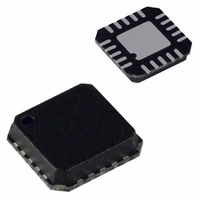
IC PLL FREQ SYNTHESIZER 20LFCSP
Manufacturer
Analog Devices Inc
Type
Clock/Frequency Synthesizer (RF/IF)r
Datasheet
1.ADF4212LBCPZ-RL.pdf
(28 pages)
Specifications of ADF4212LBCP-REEL7
Rohs Status
RoHS non-compliant
Pll
Yes
Input
CMOS
Output
Clock
Number Of Circuits
1
Ratio - Input:output
3:1
Differential - Input:output
Yes/Yes
Frequency - Max
2.4GHz
Divider/multiplier
Yes/No
Voltage - Supply
2.7 V ~ 3.3 V
Operating Temperature
-40°C ~ 85°C
Mounting Type
Surface Mount
Package / Case
20-LFCSP
Frequency-max
2.4GHz


ADF4212L
PROGRAM MODES
Table 8 and Table 10 show how to set up the program modes in
the ADF4212L. The following should be noted:
•
•
•
IF AND RF POWER-DOWN
It is possible to program the ADF4210 family for either synchron-
ous or asynchronous power-down on either the IF or RF side.
Synchronous IF Power-Down
Programming a 1 to P7 of the ADF4212L initiates a power-
down. If P2 of the ADF4212L has been set to 0 (normal
operation), a synchronous power-down is conducted. The
device automatically puts the charge pump into three-state
mode and completes the power-down.
Asynchronous IF Power-Down
If P2 of the ADF4212L has been set to 1 (the IF charge pump in
three-state mode) and P7 is subsequently set to 1, an asynchronous
power-down is conducted. The device goes into power-down on
the rising edge of LE, which latches the 1 to the IF power-down
bit (P7).
Synchronous RF Power-Down
Programming a 1 to P16 of the ADF4212L initiates a power-
down. If P10 of the ADF4212L has been set to 0 (normal
operation), a synchronous power-down is conducted. The
device automatically puts the charge pump into three-state
mode and then completes the power-down.
Asynchronous RF Power-Down
If P10 of the ADF4212L has been set to 1 (the RF charge pump in
three-state mode) and P16 is subsequently set to 1, an asynchron-
ous power-down is conducted. The device goes into power-down
on the rising edge of LE, which latches the 1 to the RF power-down
bit (P16).
IF and RF analog lock detect indicate when the PLL is in
lock. When the loop is locked and either IF or RF analog
lock detect is selected, the MUXOUT pin shows a logic
high with narrow, low-going pulses. When the IF/RF
analog lock detect is chosen, the locked condition is
indicated only when both IF and RF loops are locked.
The IF counter reset mode resets the R, A, and B counters
in the IF section and puts the IF charge pump into three-
state mode. The RF counter reset mode resets the R, A, and
B counters in the RF section and puts the RF charge pump
into three-state. The IF and RF counter reset mode does
both of the above. Upon removal of the reset bits, the A
and B counters resume counting in close alignment with
the R counter. (Maximum error is one prescaler output cycle.)
The fastlock mode uses MUXOUT to switch a second loop
filter damping resistor to ground during fastlock operation.
Activation of fastlock occurs whenever RF CP gain in the
RF reference counter is set to 1.
Rev. C | Page 20 of 28
Activation of either synchronous or asynchronous power-down
forces the IF/RF loop’s R and A/B dividers to their load state
conditions, and the IF/RF input section is debiased to a high
impedance state.
The REF
RF power-downs are set.
The input register and latches remain active and are capable of
loading and latching data during all power-down modes.
The IF/RF section of the device returns to normal powered-up
operation immediately upon LE latching a 0 to the appropriate
power-down bit.
IF SECTION
Programmable IF Reference (R) Counter
If Control Bits[C2:C1] = 00, the data is transferred from the
input shift register to the 15-bit IF R counter. Table 8 shows the
input shift register data format for the IF R counter and the
divide ratios that are possible.
IF Phase Detector Polarity
P1 sets the IF phase detector polarity. When the IF VCO
characteristics are positive, P1 should be set to 1. When
the IF VCO characteristics are negative, it should be set to 0.
See Table 8.
IF Charge Pump Three-State
P2 puts the IF charge pump into three-state mode when
programmed to a 1. It should be set to 0 for normal operation.
See Table 8.
IF Program Modes
Table 8 shows how to set up the program modes in the
ADF4212L.
IF Charge Pump Currents
IFCP2, IFCP1, and IFCP0 program the current setting for the
IF charge pump. See Table 8.
Programmable IF N Counter
If Control Bits[C2:C1] = 01, the data in the input register is
used to program the IF N (A + B) counter. The N counter
consists of a 6-bit swallow counter (A counter) and 12-bit
programmable counter (B counter). Table 9 shows the input
register data format for programming the IF A and B counters
and the divide ratios possible.
IF Prescaler Value
P5 and P6 in the IF N counter latch set the IF prescaler values.
See Table 9.
IN
oscillator circuit is disabled only if both the IF and
Related parts for ADF4212LBCP-REEL7
Image
Part Number
Description
Manufacturer
Datasheet
Request
R

Part Number:
Description:
±1.7g Dual-Axis IMEMS Accelerometer Evaluation Board
Manufacturer:
Analog Devices Inc
Datasheet:

Part Number:
Description:
Inertial Sensor Evaluation System
Manufacturer:
Analog Devices Inc
Datasheet:
Part Number:
Description:
Manufacturer:
Analog Devices Inc
Datasheet:
Part Number:
Description:
Manufacturer:
Analog Devices Inc
Datasheet:
Part Number:
Description:
Manufacturer:
Analog Devices Inc
Datasheet:
Part Number:
Description:
Manufacturer:
Analog Devices Inc
Datasheet:
Part Number:
Description:
Manufacturer:
Analog Devices Inc
Datasheet:
Part Number:
Description:
Manufacturer:
Analog Devices Inc
Datasheet:
Part Number:
Description:
Manufacturer:
Analog Devices Inc
Datasheet:
Part Number:
Description:
Manufacturer:
Analog Devices Inc
Datasheet:
Part Number:
Description:
Manufacturer:
Analog Devices Inc
Datasheet:
Part Number:
Description:
Manufacturer:
Analog Devices Inc
Datasheet:
Part Number:
Description:
Manufacturer:
Analog Devices Inc
Datasheet: