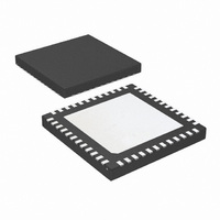
LMK03200ISQE/NOPB National Semiconductor, LMK03200ISQE/NOPB Datasheet - Page 35

LMK03200ISQE/NOPB
Manufacturer Part Number
LMK03200ISQE/NOPB
Description
IC CLOCK CONDITIONER PREC 48-LLP
Manufacturer
National Semiconductor
Type
Clock Conditionerr
Datasheet
1.LMK03200ISQENOPB.pdf
(40 pages)
Specifications of LMK03200ISQE/NOPB
Pll
Yes
Input
Clock
Output
LVDS, LVPECL
Number Of Circuits
1
Ratio - Input:output
1:9
Differential - Input:output
Yes/Yes
Frequency - Max
1.296GHz
Divider/multiplier
Yes/No
Voltage - Supply
3.15 V ~ 3.45 V
Operating Temperature
-40°C ~ 85°C
Mounting Type
Surface Mount
Package / Case
48-LLP
Frequency-max
1.296GHz
Lead Free Status / RoHS Status
Lead free / RoHS Compliant
Other names
LMK03200ISQETR
Available stocks
Company
Part Number
Manufacturer
Quantity
Price
Company:
Part Number:
LMK03200ISQE/NOPB
Manufacturer:
NSC
Quantity:
72
FIGURE 10. Differential LVPECL Operation, DC Coupling,
FIGURE 9. Differential LVPECL Operation, DC Coupling
Thevenin Equivalent
30088718
30088721
35
3.7.2 Termination for AC Coupled Differential Operation
AC coupling allows for shifting the DC bias level (common
mode voltage) when driving different receiver standards.
Since AC coupling prevents the driver from providing a DC
bias voltage at the receiver it is important to ensure the re-
ceiver is biased to its ideal DC level.
When driving LVDS receivers with an LVDS driver, the signal
may be AC coupled by adding DC blocking capacitors, how-
ever the proper DC bias point needs to be established at the
receiver. One way to do this is with the termination circuitry in
Figure
LVPECL drivers require a DC path to ground. When AC cou-
pling an LVPECL signal use 120 Ω emitter resistors close to
the LVPECL driver to provide a DC path to ground as shown
in
be biased to the DC bias level (common mode voltage) spec-
ified by the receiver. The typical DC bias voltage (common
mode voltage) for LVPECL receivers is 2 V. A Thevenin
equivalent circuit (82 Ω resistor connected to Vcc and a 120
Ω resistor connected to ground with the driver connected to
the junction of the 82 Ω and 120 Ω resistors) is a valid termi-
nation as shown in
Thevenin circuit is different from the DC coupled example in
Figure
FIGURE 12. Differential LVPECL Operation, AC Coupling,
FIGURE 11. Differential LVDS Operation, AC Coupling
Figure
11.
10.
12. For proper receiver operation, the signal should
Thevenin Equivalent
Figure 12
for Vcc = 3.3 V. Note this
www.national.com
30088719
30088717


