SY58605UMG TR Micrel Inc, SY58605UMG TR Datasheet - Page 5
SY58605UMG TR
Manufacturer Part Number
SY58605UMG TR
Description
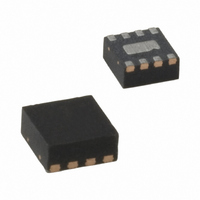
IC BUFFER LVDS 3.2GBPS FSI 8-MLF
Manufacturer
Micrel Inc
Series
Precision Edge®r
Type
Buffer/Driverr
Datasheet
1.SY58605UMG_TR.pdf
(12 pages)
Specifications of SY58605UMG TR
Number Of Circuits
1
Ratio - Input:output
1:1
Differential - Input:output
Yes/Yes
Input
CML, LVDS, LVPECL
Output
LVDS
Frequency - Max
3GHz
Voltage - Supply
2.375 V ~ 2.625 V
Operating Temperature
-40°C ~ 85°C
Mounting Type
Surface Mount
Package / Case
8-MLF®, QFN
Frequency-max
3GHz
Number Of Outputs
2
Operating Supply Voltage (max)
2.625V
Operating Temp Range
-40C to 85C
Propagation Delay Time
0.42ns
Operating Supply Voltage (min)
2.375V
Mounting
Surface Mount
Pin Count
8
Operating Supply Voltage (typ)
2.5V
Package Type
MLF
Input Frequency
3GHz
Duty Cycle
53%
Operating Temperature Classification
Industrial
Lead Free Status / RoHS Status
Lead free / RoHS Compliant
Lead Free Status / RoHS Status
Compliant, Lead free / RoHS Compliant
Other names
576-1596-2


Micrel, Inc.
AC Electrical Characteristics
V
Notes:
8.
9.
10. Deterministic jitter is measured at 2.5Gbps with both K28.5 and 2
11. Cycle-to-cycle jitter definition: the variation period between adjacent cycles over a random sample of adjacent cycle pairs. t
12. Total jitter definition: with an ideal clock input frequency of ≤ f
August 2007
Symbol
f
t
t
t
t
CC
MAX
PD
Skew
Jitter
r,
t
f
Part-to-part skew is defined for two parts with identical power supply voltages at the same temperature and no skew at the edges at the
respective inputs.
Random jitter is measured with a K28.7 pattern, measured at ≤ f
where T is the time between rising edges of the output signal.
more than the specified peak-to-peak jitter value.
= +2.5V ±5%, R
Parameter
Maximum Frequency
Propagation Delay
Part-to-Part Skew
Data
Clock
Output Rise/Fall Times
(20% to 80%)
Duty Cycle
L
= 100Ω across the outputs, Input t
Random Jitter
Deterministic Jitter
Cycle-to-Cycle Jitter
Total Jitter
IN-to-Q
Condition
NRZ Data
V
Note 8
Note 9
Note 10
Note 11
Note 12
At full output swing.
Differential I/O
V
IN
OUT
: 100mV-200mV
200mV-800mV
> 200mV
MAX
MAX
r
(device), no more than one output edge in 10
/t
23
–1 PRBS pattern.
f
.
: <300ps; T
5
A
= –40°C to +85°C, unless otherwise stated.
Clock
hbwhelp@micrel.com
Min
170
130
3.2
2.0
35
47
12
output edges will deviate by
Typ
280
200
60
3
or (408) 955-1690
M9999-082907-B
JITTER
Max
420
300
135
100
10
10
53
1
1
SY58605U
_
CC
= T
Units
ps
ps
Gbps
n
GHz
ps
ps
ps
ps
ps
ps
–T
%
RMS
RMS
PP
PP
n+1
,
Related parts for SY58605UMG TR
Image
Part Number
Description
Manufacturer
Datasheet
Request
R

Part Number:
Description:
Manufacturer:
Micrel Inc
Datasheet:
Part Number:
Description:
Manufacturer:
Micrel Inc
Datasheet:
Part Number:
Description:
Manufacturer:
Micrel Inc
Datasheet:
Part Number:
Description:
Manufacturer:
Micrel Inc
Datasheet:
Part Number:
Description:
Manufacturer:
Micrel Inc
Datasheet:
Part Number:
Description:
Manufacturer:
Micrel Inc
Datasheet:
Part Number:
Description:
Manufacturer:
Micrel Inc
Datasheet:
Part Number:
Description:
Manufacturer:
Micrel Inc
Datasheet:
Part Number:
Description:
Manufacturer:
Micrel Inc
Datasheet:
Part Number:
Description:
Manufacturer:
Micrel Inc
Datasheet:
Part Number:
Description:
Manufacturer:
Micrel Inc
Datasheet:
Part Number:
Description:
Manufacturer:
Micrel Inc
Datasheet:
Part Number:
Description:
Manufacturer:
Micrel Inc
Datasheet:
Part Number:
Description:
Manufacturer:
Micrel Inc
Datasheet: