CUB7CCR0 Red Lion Controls, CUB7CCR0 Datasheet - Page 4
CUB7CCR0
Manufacturer Part Number
CUB7CCR0
Description
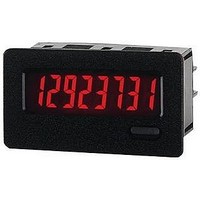
COUNTER 8-DIGIT LV RED BACKLIGHT
Manufacturer
Red Lion Controls
Type
High Speed Counterr
Datasheet
1.CUB7CCS0.pdf
(8 pages)
Specifications of CUB7CCR0
Count Rate
10kHz
Number Of Digits/alpha
8
Input Type
Voltage
Voltage - Supply
None Required (Battery Included)
Display Type
LCD Red Backlight
No. Of Digits / Alpha
8
Digit Height
8.9mm
Counting Speed
10kHz
Operating Temperature Range
0°C To +50°C
Signal Input Type
Contact
Display Mode
LCD Positive Reflective
Character Size
0.35"
Application
Miniature Counter
Brand/series
CUB7
Dimensions
1.10 × 2.00 × 1.64 In.
Display Digit Height
8/0.35" High
Mounting Type
Panel
Number Of Digits
8
Primary Type
Counter
Signal, Input
1.5 VDC or 50-250 VDC/VAC
Termination
Wire or Optional Plug-In Terminal
Voltage, Supply
Internal 3.6 VDC Battery
Backlighting Color
Red
Rohs Compliant
Yes
Backlight Power
9-28VDC
Counter Supply Voltage
9-28VDC
Lead Free Status / RoHS Status
Lead free / RoHS Compliant


appropriately prior to wiring.
or both.
the low voltage input units or the single DIP switch on the high voltage input
units. (See 2.0 Setting the DIP Switches for switch location)
Note: Placing the KEY DISABLE/ENABLE DIP switch in the OFF position, disables all front panel keys.
keypad with the DIP switch and press the SEL key. The currently programmed
time range will be displayed (example 2222222.2 = time range 2). To change the
range, press the RST key. The ranges will cycle from 0-8 and back to 0. To enter
your time range, press the SEL key and the unit will retain the current time range
and return back to normal.
2.0 S
3.0 P
4.0 R
Low voltage input units have 3 DIP switches that must be positioned
The display may be reset to zero via the front RST key, the remote reset input
The front RST key must be enabled for front panel reset. DIP switch # 3 on
The CUB7 Timer has 9 time ranges. To change ranges, enable the front
ON
SEL
1 2 3
ETTING THE
ROGRAMMING
ESETTING
85374216
Low Voltage Input Unit
Bottom of Unit
Rear of Unit
T
HE
DIP S
T
RST
D
HE
ISPLAY
WITCHES
T
4
IME
keypad.
between the reset input (blue wire) and the common (black wire). When the
optional terminal blocks are used, see 5.0 Wiring The Meter, for the appropriate
reset input terminal and the common terminal.
DISPLAY DURING
PROGRAMMING
High voltage input units have 1 DIP switch to enable or disable the front bezel
The remote reset is activated via an external momentary contact closure
333333333
555555555
00000.000
2222222.2
4444444.4
666666.66
7777777.7
88888888
111111.11
ON
1
R
ANGE
TIMER RANGE
0.001 SEC
0.01 SEC
0.1 SEC
1 SEC
0.1 MIN
1 MIN
0.01 HR
0.1 HR
1 HR
High Voltage Input Unit
Bottom of Unit
Rear of Unit