CUB7CCR0 Red Lion Controls, CUB7CCR0 Datasheet - Page 3
CUB7CCR0
Manufacturer Part Number
CUB7CCR0
Description
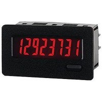
COUNTER 8-DIGIT LV RED BACKLIGHT
Manufacturer
Red Lion Controls
Type
High Speed Counterr
Datasheet
1.CUB7CCS0.pdf
(8 pages)
Specifications of CUB7CCR0
Count Rate
10kHz
Number Of Digits/alpha
8
Input Type
Voltage
Voltage - Supply
None Required (Battery Included)
Display Type
LCD Red Backlight
No. Of Digits / Alpha
8
Digit Height
8.9mm
Counting Speed
10kHz
Operating Temperature Range
0°C To +50°C
Signal Input Type
Contact
Display Mode
LCD Positive Reflective
Character Size
0.35"
Application
Miniature Counter
Brand/series
CUB7
Dimensions
1.10 × 2.00 × 1.64 In.
Display Digit Height
8/0.35" High
Mounting Type
Panel
Number Of Digits
8
Primary Type
Counter
Signal, Input
1.5 VDC or 50-250 VDC/VAC
Termination
Wire or Optional Plug-In Terminal
Voltage, Supply
Internal 3.6 VDC Battery
Backlighting Color
Red
Rohs Compliant
Yes
Backlight Power
9-28VDC
Counter Supply Voltage
9-28VDC
Lead Free Status / RoHS Status
Lead free / RoHS Compliant


INSTALLATION ENVIRONMENT
operating temperature and provides good air circulation. Placing the unit near
devices that generate excessive heat should be avoided.
Do NOT use solvents.
the bezel. Do not use tools of any kind (screwdrivers, pens, pencils, etc.) to
operate the keypad of the unit.
Installation
outdoor use, when properly installed. The units are intended to be mounted into
an enclosed panel. The viewing window and reset button are factory sealed for
a washdown environment. A sponge rubber gasket and mounting clip are
provided for installing the unit in the panel cut-out.
1. Cut panel opening to specified dimensions. Remove burrs and clean around
2. Carefully remove and discard the center section of the gasket. Slide the panel
3. Install the CUB7 unit through the panel cut-out until the front bezel flange
4. Slide the mounting clip over the rear of the unit until the clip is against the
Note: It is necessary to hold the unit in place when sliding mounting clip into
1.0 I
The unit should be installed in a location that does not exceed the maximum
The bezel should be cleaned only with a soft cloth and neutral soap product.
Continuous exposure to direct sunlight may accelerate the aging process of
The CUB7 series of products meets NEMA 4X/IP65 requirements for
The following procedure assures proper installation:
panel opening.
gasket over the rear of the unit to the back of the bezel. Insert the mounting
screws onto both sides of mounting clip. The tip of the screw should NOT
project from the hole in the mounting clip.
contacts the panel.
back of the panel. The mounting clip has latching features which engage into
mating features on the CUB7 housing.
position.
NSTALLING THE
Bezel
Gasket
Mounting
Clip
M
ETER
Latching Feature
3
5. Alternately tighten each screw to ensure uniform gasket pressure. Visually
6. If gasket is not adequately compressed and the mounting screws can no longer
7. Repeat from step #5 for tightening mounting screws.
Mounting
inspect the front panel gasket. The gasket should be compressed to about 75
to 80% of its original thickness. If not, gradually turn mounting screws to
further compress gasket.
be turned, loosen mounting screws, and check that mounting clip is latched
as close as possible to the panel.
Screw
(45
1.77
+0.6
-0.0
+0.024
-0.000
)
(22.2
0.88
+0.012
+0.3
-0.000
-0.0
)