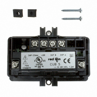
CUB5R000 Red Lion Controls, CUB5R000 Datasheet - Page 7

CUB5R000
Manufacturer Part Number
CUB5R000
Description
COUNTER/RATE IND DUAL REFL DISPL
Manufacturer
Red Lion Controls
Series
CUB5r
Type
Counter/Rate Indicatorr
Datasheet
1.CUB5RLY0.pdf
(16 pages)
Specifications of CUB5R000
Count Rate
20kHz
Number Of Digits/alpha
8
Input Type
Voltage, Switch Closure, Transistor Switch
Voltage - Supply
9 V ~ 28 V
Display Type
LCD Non-Backlit
No. Of Digits / Alpha
8
Digit Height
11.7mm
Counting Speed
20kHz
Operating Temperature Range
-35°C To +75°C
Signal Input Type
Current
Character Size
0.46"
Ip/nema Rating
IP65 / NEMA 4X
Accuracy
±0.01% %
Connection Type
Screw
Counter Type
Up⁄Down & Rate
Cut Out, Panel
2.68×1.3 "
Dimensions
2.95"L×1.86"W×1.54"H
Display Digit Height
0.46 "
Display Range
-9999999 to +99999999
Frequency, Operating
20 kHz (Max.)
Function
Counter/Rate Indicator
Material, Casing
Plastic
Memory Type
EEPROM
Mounting Type
Panel
Number Of Digits
8
Output Type
Relay
Primary Type
Electronic
Range, Measurement
-9999999 to 999999
Special Features
Programmable
Standards
CE Marked
Temperature, Operating, Range
-35 to +75 °C
Terminal Type
Screw Terminal
Termination
Screw Terminal
Voltage, Supply
9 to 28 VDC
Weight
3.2 Oz.
Memory
Nonvolatile EEPROM
User Input
Programmable, Connect to Common to Activate Function
Rate Minimum Input Frequency
0.01 Hz
Rate Maximum Frequency
20 kHz
Operating Temperature
0 to 60°C
Panel Cutout
2.68" × 1.30"
Counter Supply Voltage
9-28VDC
Rohs Compliant
Yes
Lead Free Status / RoHS Status
Lead free / RoHS Compliant
Output Type
-
Lead Free Status / Rohs Status
RoHS Compliant part
Other names
RLC121
Available stocks
Company
Part Number
Manufacturer
Quantity
Price
Company:
Part Number:
CUB5R000
Manufacturer:
Red Lion Controls
Quantity:
135
mode or batch counter).
actions are shown in the boxes below. For simple counting applications, it is
recommended to use Count with Direction for the count mode. Simply leave the
direction input unconnected.
affect Counter A scale factor calculations.
This reset action applies to all Counter A resets, except a setpoint generated
Counter Auto Reset programmed in Module 4.
desired process value. A scale factor of 1.0000 will result in the display of the
actual number of input counts. (Details on scaling calculations are explained at
the end of this section.)*
Count Mode parameter chart.
CmtA ScF
CmtA rSt
CmtA dir
SEL
INP A-b
CntA dP
6.1 MODULE 1 - I
1-INPUt
INP A-b
Add Add
Add Sub
Shaded area selections only apply when Counter B is enabled (Dual Counter
Select the count mode that corresponds with your application. The input
Note: The Rate indicator signal is derived from Input A in all count modes.
This selects the decimal point position for Counter A. The selection will also
The number of input counts is multiplied by the scale factor to obtain the
When Counter A is reset, it returns to Zero or Counter A Count Load value.
Reverse (
DISPLAY
RAtE Cnt
dUAL Cnt
Count
Cnt ud
qUAd 1
qUAd 2
qUAd 4
Mode
to 2Ero
Cnt ud
01. 0 000
rEV
Decimal Point
Count with Direction
Rate/Counter
Dual Counter
Quadrature x1
Quadrature x2
Quadrature x4
2 Input Add/Add
2 Input Add/Subtract
CntA dP
) switches the normal Counter A count direction shown in the
Counter A
NOr
COUNTER A DECIMAL POSITION
COUNTER A COUNT DIRECTION
COUNTER A SCALE FACTOR
0
COUNTER A RESET ACTION
MODE
RAtE Cnt
dUAL Cnt
CntA ScF
Scale Factor
Counter A
COUNT MODE
Cnt ud
to 2Ero
NOr
00. 0 001
CntA rSt
Reset Action
0. 0
Counter A
INPUT A ACTION
to
Counter A Add
Counter A Add
Counter A Add
0
Counter A
Rate only
99. 9 999
Count A
Count A
Count A
rEV
qUAd 1
qUAd 2
qUAd 4
0. 0 00
to CtLd
0. 0 0
NPUT
CntA dir
Counter A
Direction
Count
Counter A Direction
Counter A Subtract
0. 0 0000
INPUT B ACTION
0. 0 000
Counter B Add
Counter A Add
Counter A Add
Add Add
Add Sub
PARAMETER MENU
Quad A
Quad A
Quad A
S
CntA Ld
Count Load
Counter A
Value
ETUP
Cntb bAt
Batch Count
Counter B
Enable
7
P
ARAMETERS
affect Counter B scale factor calculations.
activations of the selected setpoint(s). The count source for the batch counter
can be SP1, SP2 or both. Batch counting is available in all count modes except
Dual Counter, which uses an external input signal for Counter B. This
parameter only appears if a Setpoint Output option card is installed.
obtain the desired process value. A scale factor of 1.0000 will result in the
display of the actual number of input or batch counts. (Details on scaling
calculations are explained at the end of this section.)*
The selected counter(s) will reset at each meter power-up.
* For value entry instructions, refer to selection/value entry in the Programming
CmtA Ld
Cmtb bAt
RSt P-UP
Cntb ScF
Cntb dP
This selects the decimal point position for Counter B. The selection will also
The number of input or batch counts is multiplied by the scale factor to
The Meter section.
Counter A resets to this value if Reset to Count Load action is selected.
The Counter B batch count function internally counts the number of output
Cntb dP
Decimal Point
Counter B
00000500
Dual Count or Batch
01. 0 000
COUNTER B BATCH COUNT ENABLE
Only
COUNTER A COUNT LOAD VALUE
COUNTER B DECIMAL POSITION
COUNTER RESET AT POWER-UP
NO
NO
Cntb ScF
Scale Factor
Counter B
COUNTER B SCALE FACTOR
0
(
00. 0 001
1-INPUt
Counter Reset
RSt P-UP
at Power-up
-9999999
yES
NO
to
SP1
0. 0
NO
99. 9 999
0
USEr INP
to
)
Count A
User Input
Function
99999999
SP1-2
0. 0 00
SP2
0. 0 0
NO
Dual Count
USEr ASN
User Input
Assignment
both A-b
or Batch
Count b
Only
0. 0 0000
0. 0 000
Pro


