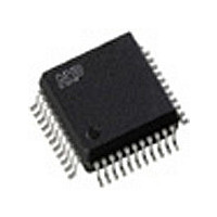
SAA7113H NXP Semiconductors, SAA7113H Datasheet - Page 8

SAA7113H
Manufacturer Part Number
SAA7113H
Description
Manufacturer
NXP Semiconductors
Datasheet
1.SAA7113H.pdf
(75 pages)
Specifications of SAA7113H
Video Resolution (max)
720Pixels
Pin Count
44
Package Type
PQFP
Lead Free Status / RoHS Status
Compliant
Available stocks
Company
Part Number
Manufacturer
Quantity
Price
Part Number:
SAA7113H
Manufacturer:
PHILIPS
Quantity:
20 000
Company:
Part Number:
SAA7113H/V2
Manufacturer:
NXP
Quantity:
12 000
Part Number:
SAA7113H/V2
Manufacturer:
NXP/恩智浦
Quantity:
20 000
Company:
Part Number:
SAA7113H/V2,518
Manufacturer:
Sigma Designs Inc
Quantity:
10 000
Philips Semiconductors
9397 750 14232
Product data sheet
8.2.1 Clamping
8.2.2 Gain control
The clamp control circuit controls the correct clamping of the analog input signals. The
coupling capacitor is also used to store and filter the clamping voltage. An internal digital
clamp comparator generates the information with respect to clamp-up or clamp-down.
The clamping levels for the two ADC channels are fixed for luminance (120) and
chrominance (256). Clamping time in normal use is set with the HCL pulse on the back
porch of the video signal.
The gain control circuit receives (via the I
amplifiers or controls one of these amplifiers automatically via a built-in Automatic Gain
Control (AGC) as part of the Analog Input Control (AICO). The AGC for luminance is used
to amplify a CVBS or Y signal to the required signal amplitude, matched to the ADCs input
voltage range. The AGC active time is the sync bottom of the video signal.
Signal (white) peak control limits the gain at signal overshoots. The flow charts
(see
voltage variation within the specified range is automatically eliminated by clamp and
automatic gain control.
Fig 4. Analog line with clamp (HCL) and gain range (HSY)
Fig 5. Automatic gain range
Figure 7
and
Figure
(1 V (p-p) 18/56 )
Rev. 02 — 9 May 2005
8) show more details of the AGC. The influence of supply
255
60
1
analog input level
0 dB
3 dB
6 dB
analog line blanking
GAIN
HSY
maximum
minimum
2
range 9 dB
C-bus) the static gain levels for the two analog
TV line
CLAMP
HCL
ADC input level
mhb325
controlled
mgl065
© Koninklijke Philips Electronics N.V. 2005. All rights reserved.
9-bit video input processor
0 dB
SAA7113H
8 of 75


