PD2435 OSRAM Opto Semiconductors Inc, PD2435 Datasheet
PD2435
Specifications of PD2435


Related parts for PD2435


PD2435 Summary of contents
Page 1
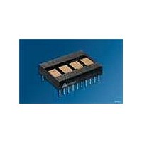
... Built-in CMOS Control Functions PD353X FEATURES • Four Dot Matrix Characters in High Efficiency Red, Red, and Bright Green - PD2435/6/7, 5.08 mm (0.200") High - PD3535/6/7, 6.86 mm (0.270") High - PD4435/6/7, 11.43 mm (0.45") High • Built-in Memory, Decoders, Multiplexer and Drivers • Wide Viewing Angle, X Axis ± 55°, Y Axis ± 65° ...
Page 2
... Ordering Information Type PD2435 PD2436 PD2437 PD3535 PD3536 PD3537 PD4435 PD4436 PD4437 2006-01-23 PD243X, PD353X, PD443X Color of Emission Character Height mm (inch) high efficiency red red bright green high efficiency red red bright green high efficiency red red bright green 2 Ordering Code Q68000A3561 5 ...
Page 3
Maximum Ratings Parameter Operating temperature range Storage temperature range Viewing angle (off normal axis DC Supply Voltage Input Voltage Relative to GND (all inputs) Solder temperature 1.59 mm (0.063“) below seating plane, t < 5.0 s Characteristics ...
Page 4
PD243X 6.35 (0.250) 3.18 (0.125) Pin 1 Location PD353X 0.46 (0.018) x 0.31 (0.012) typ. 6.35 (0.250) 4.45 (0.175) 2006-01-23 Pin 1 Indicator EIA Date Code Luminous PD243X Z Intensity OSRAM YYWW V Code 2.54 (0.100) typ. 0.46 (0.018) x ...
Page 5
PD443X 7.62 (0.300) 1.27 (0.050) Top View 2006-01-23 Dimensions in mm (inch) Pin 1 Indicator EIA Date Code Part No. Luminous Intensity Code PD443X Z OSRAM YYWW V 2.54 (0.100) typ. 0.46 (0.018) x 0.31 (0.012) typ. ±0.05 (0.002) 38.1 ...
Page 6
Timing Characteristics—Data “Write” Cycle CE0, CE1 T CES A0 D0– ACC Notes: 1. Wait 1.0 µs between any Reads or Writes after writing a Control Word with a Clear (D7=1). ...
Page 7
... CLKSEL CLOCK SELECT determines the action of pin 2. CLK I/O, see the section on Cascading for an example. 4 RST Reset. Used to synchronize blinking. Will not clear the display. The reset pulse should be less than CE1 Chip enable (active high). 6 CE0 Chip enable (active low). ...
Page 8
... Input Buffering If a cable length of 6 inches or more is used, all inputs to the display should be buffered with a tri-state non-inverting buffer mounted as close to the display as conveniently possible. Recommended buffers are: 74LS245 for the data lines and 74LS244 for the control lines. ...
Page 9
... Digit 3 (leftmost) Bit D7 of any of the display digit locations is used to allow an at- tribute to be assigned to that digit. The attributes are discussed in the next section. If Bit D7 is set to a one, that character will be dis- played using the attribute. If bit D7 is cleared, the character will dis- play normally ...
Page 10
... Word bit D4 is set, and D3=D2=0) the character will remain in memory and can be revealed again by clearing D4 in the Control Word. Blink (D5): The entire display can be caused to blink at a rate of approximately 2 setting bit D5 in the Control Word. This blink- ing is independent of the state all character locations. ...
Page 11
... Information loaded into the display can be either ASCII data or Control Word data. The following procedure (see also Typical Loading Sequence) will demonstrate a typical loading sequence and the resulting visual display. The word STOP is used in all of the following examples. Set Brightness Step 1 ...
Page 12
... Electrical and Mechanical Considerations The CMOS IC of the display is designed to provide resistance to both Electrostatic Discharge Damage and Latch Up due to voltage or current surges. Several precautions are strongly recommended to avoid overstressing these built-in safeguards. ESD Protection Display users should be careful to handle the devices consistent with Standard ESD protection procedures ...
Page 13
Revision History: 2006-01-23 Previous Version: 2004-12-09 Page Subjects (major changes since last revision) all Lead free device Attention please! The information describes the type of component and shall not be considered as assured characteristics. Terms of delivery and rights to ...
Page 14
... Plas- tic band-pass filters are inexpensive and effective in optimizing contrast ratios. The PD2435/3535/4435 is high efficiency red dis- play and should be matched with a long wavelength pass filter in the 570 nm to 590 nm range. The PD2436/3536/4436 is a stan- dard red display and should be matched with a long wavelength pass filter in the 600 nm to 620 nm range ...