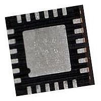
SX1233IMLTRT Semtech, SX1233IMLTRT Datasheet - Page 2

SX1233IMLTRT
Manufacturer Part Number
SX1233IMLTRT
Description
RF Transceiver Extended Bands Japan-Korea
Manufacturer
Semtech
Datasheet
1.SX1233IMLTRT.pdf
(84 pages)
Specifications of SX1233IMLTRT
Transmitting Current
95mA
Data Rate
600Kbps
Rf Ic Case Style
QFN
No. Of Pins
24
Supply Voltage Range
1.8V To 3.6V
Operating Temperature Range
-40°C To +85°C
Receiving Current
17mA
Available stocks
Company
Part Number
Manufacturer
Quantity
Price
Company:
Part Number:
SX1233IMLTRT
Manufacturer:
INFINEON
Quantity:
4 300
Section
1.
2.
3.
Rev 5 - June 2011
ADVANCED COMMUNICATIONS & SENSING
Table of contents
1.1.
1.2.
1.3.
2.1.
2.2.
2.3.
2.4.
3.1.
3.2.
3.3.
3.4.
3.5.
General Description..................................................................................................................................................................... 8
Electrical Characteristics ........................................................................................................................................................... 11
Chip Description ........................................................................................................................................................................ 16
2.4.1. Power Consumption ..................................................................................................................................................... 12
2.4.2. Frequency Synthesis .................................................................................................................................................... 12
2.4.3. Receiver........................................................................................................................................................................ 13
2.4.4. Transmitter.................................................................................................................................................................... 14
2.4.5. Digital Specification ...................................................................................................................................................... 15
3.3.1. Reference Oscillator ..................................................................................................................................................... 16
3.3.2. CLKOUT Output ........................................................................................................................................................... 17
3.3.3. PLL Architecture ........................................................................................................................................................... 17
3.3.4. Lock Time ..................................................................................................................................................................... 18
3.3.5. Lock Detect Indicator .................................................................................................................................................... 18
3.4.1. Architecture Description................................................................................................................................................ 19
3.4.2. Bit Rate Setting............................................................................................................................................................. 19
3.4.3. FSK Modulation ............................................................................................................................................................ 20
3.4.4. OOK Modulation ........................................................................................................................................................... 21
3.4.5. Modulation Shaping ...................................................................................................................................................... 21
3.4.6. Power Amplifiers........................................................................................................................................................... 21
3.4.7. Over Current Protection................................................................................................................................................ 22
3.5.1. Block Diagram .............................................................................................................................................................. 23
3.5.2. LNA - Single to Differential Buffer................................................................................................................................. 23
3.5.3. Automatic Gain Control................................................................................................................................................. 24
3.5.4. Continuous-Time DAGC ............................................................................................................................................... 25
3.5.5. Quadrature Mixer - ADCs - Decimators........................................................................................................................ 26
3.5.6. Channel Filter ............................................................................................................................................................... 26
3.5.7. DC Cancellation............................................................................................................................................................ 27
3.5.8. Complex Filter - OOK ................................................................................................................................................... 27
3.5.9. RSSI ............................................................................................................................................................................. 27
3.5.10. Cordic ......................................................................................................................................................................... 28
3.5.11. FSK Demodulator ....................................................................................................................................................... 29
3.5.12. OOK Demodulator ...................................................................................................................................................... 29
3.5.13. Bit Synchronizer.......................................................................................................................................................... 31
Simplified Block Diagram.................................................................................................................................................... 8
Pin and Marking Diagram ................................................................................................................................................... 9
Pin Description .................................................................................................................................................................. 10
ESD Notice ....................................................................................................................................................................... 11
Absolute Maximum Ratings .............................................................................................................................................. 11
Operating Range .............................................................................................................................................................. 11
Chip Specification ............................................................................................................................................................. 12
Power Supply Strategy ..................................................................................................................................................... 16
Low Battery Detector ........................................................................................................................................................ 16
Frequency Synthesis ........................................................................................................................................................ 16
Transmitter Description ..................................................................................................................................................... 19
Receiver Description ......................................................................................................................................................... 23
Page 2
DATASHEET
www.semtech.com
SX1233
Page


